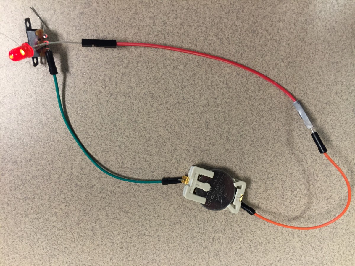
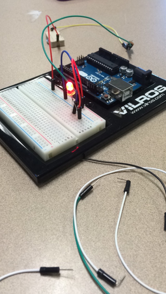
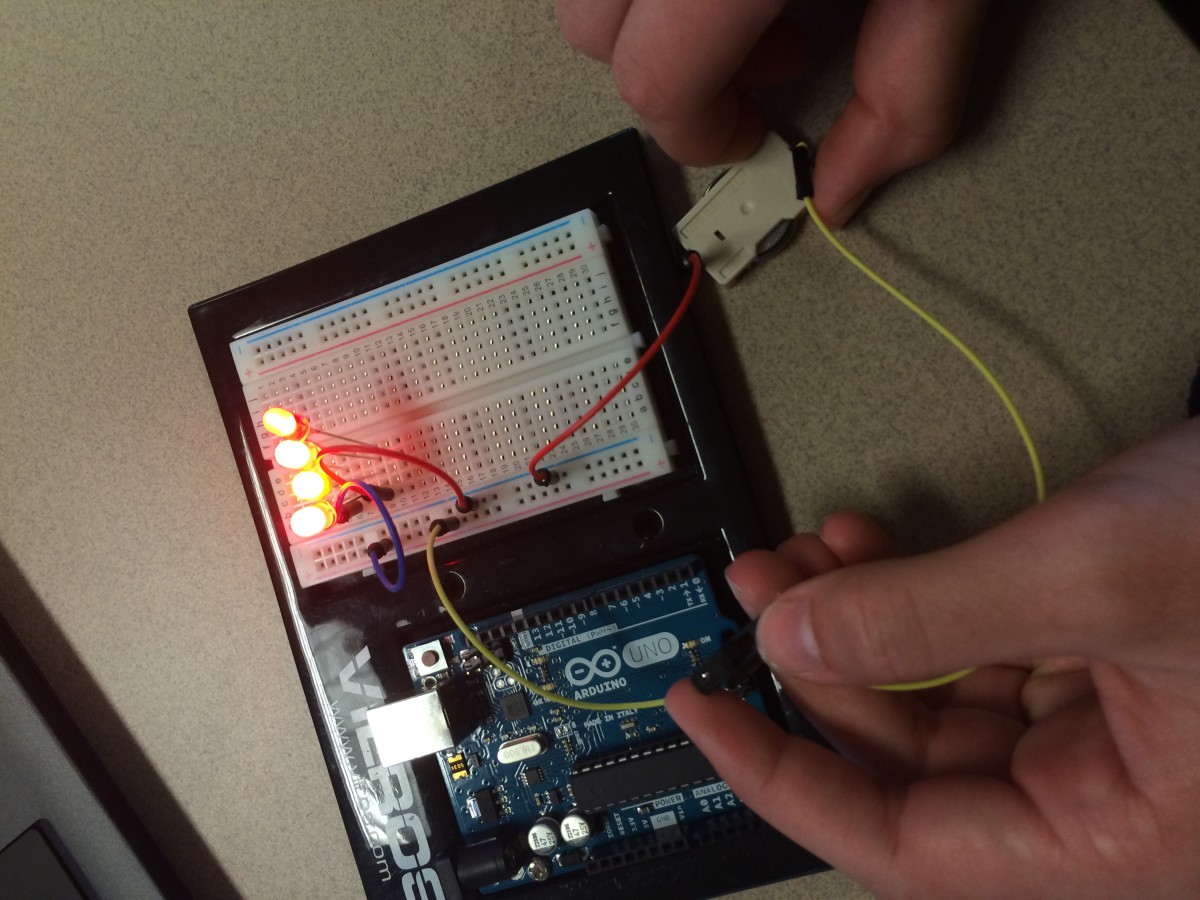
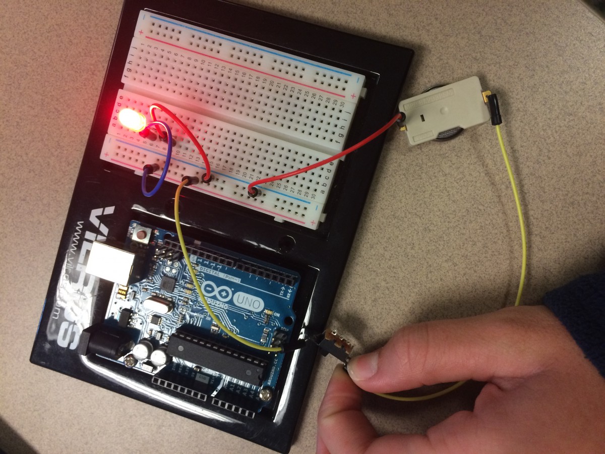
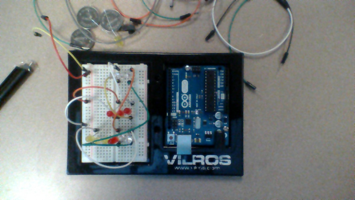
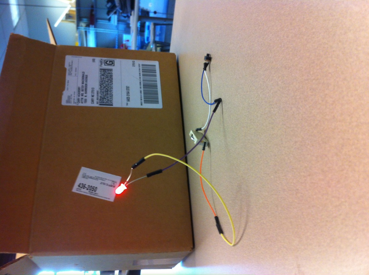
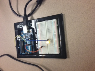
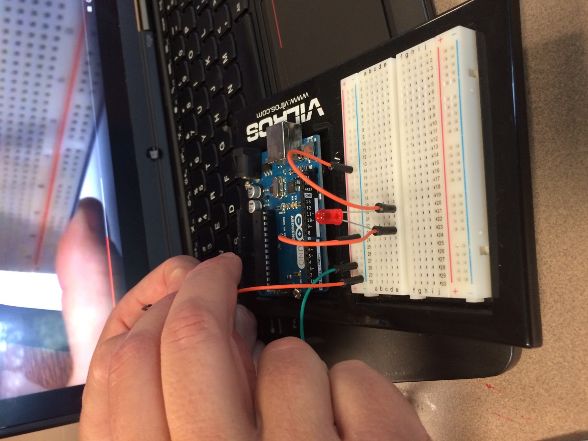
I learned about making circuits, using resistors in those circuits, and the basics of writing/ fixing code for making an LED blink every second.
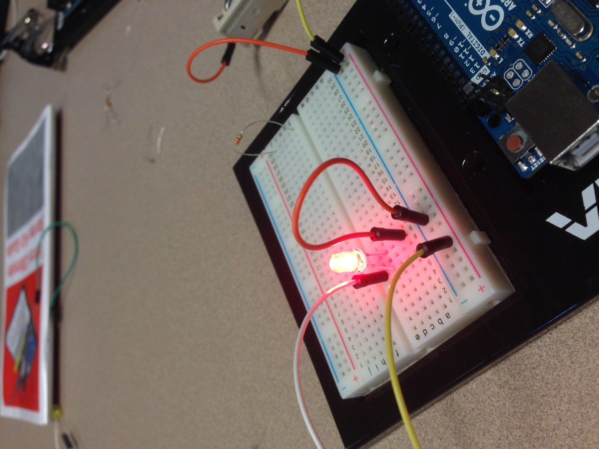
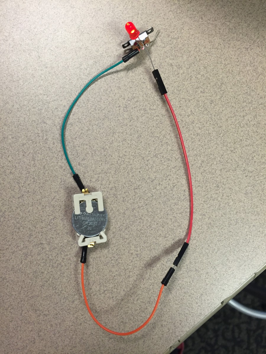
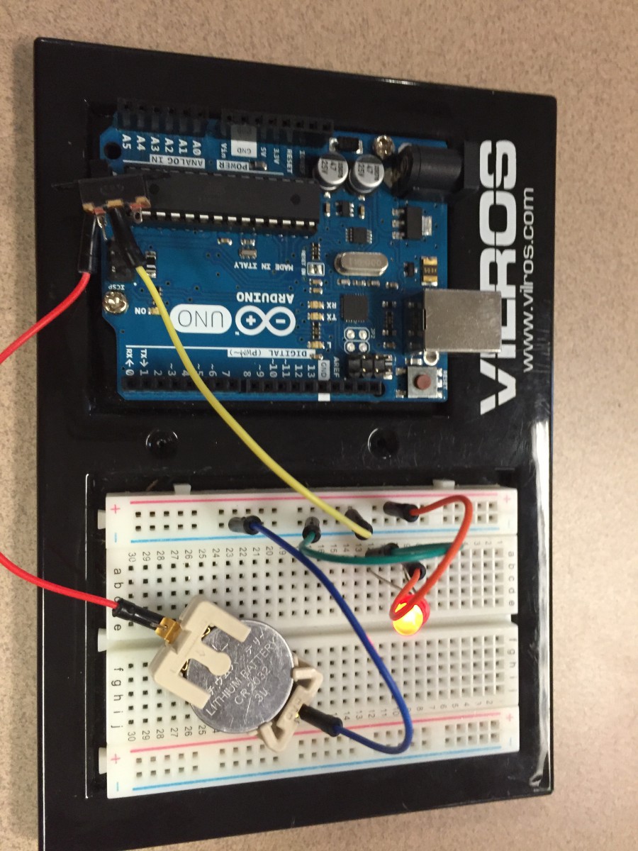
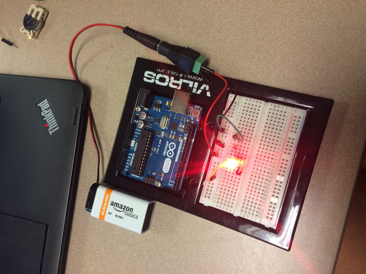
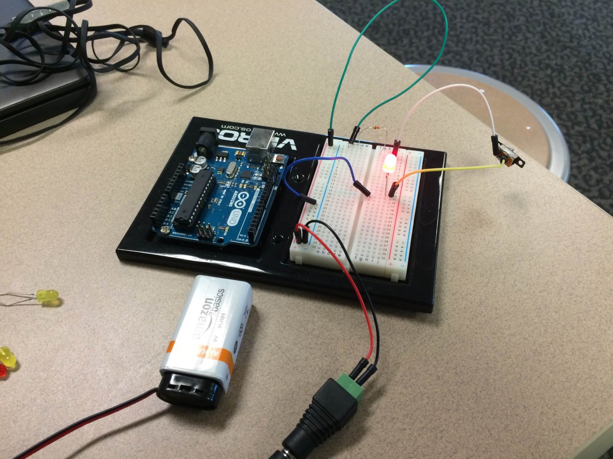
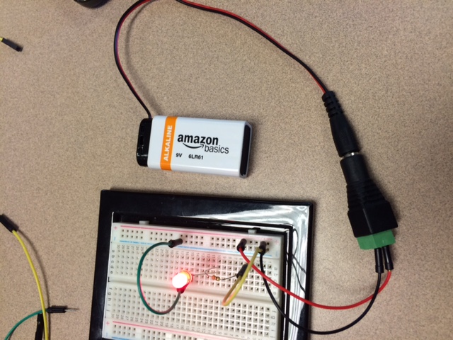
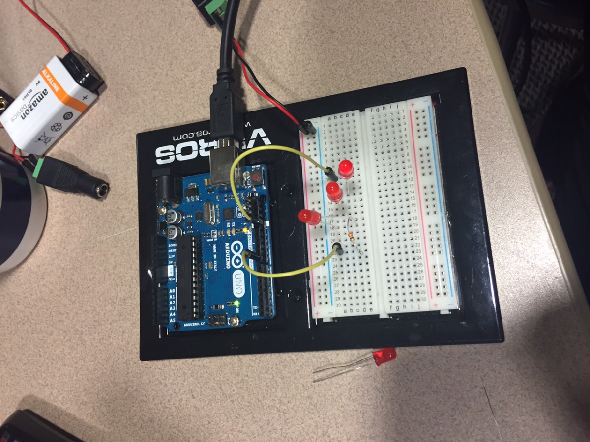
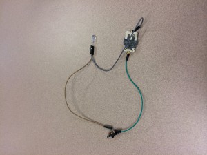
When making the circuits themselves, I learned how to make sure that the circuit is fully connected from both positive and negative leads along with a ground. I also learned to use a resistor in the middle of a circuit in order to make sure the LED it is connected to doesn’t burn out. Finally we used code to program an arduino to make an LED blink every other second. Part of the code wasn’t working perfectly, so we had to modify it to work for our purposes. Here is the code:
/*
YouTube Demo
Arduino Tutorial – LED Blink / Code Included
*/
//Sets Red to digital pin 8 and Green to digital pin 7
#define Red 8
#define Green 7
void setup()
{
//Initializes pin 8 and 7 as outputs
pinMode(Red,OUTPUT);
pinMode(Green,OUTPUT);
}
void loop()
{
//Blinking
digitalWrite(Red,HIGH); //Red on
digitalWrite(Green,LOW); //Green off
delay(500); //Wait half a second
digitalWrite(Red,LOW); //Red off
digitalWrite(Green,HIGH); //Green on
delay(500); //Wait half a second
}

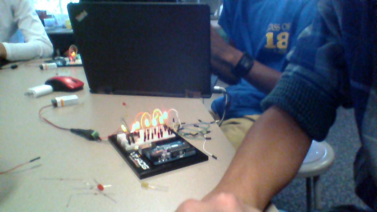
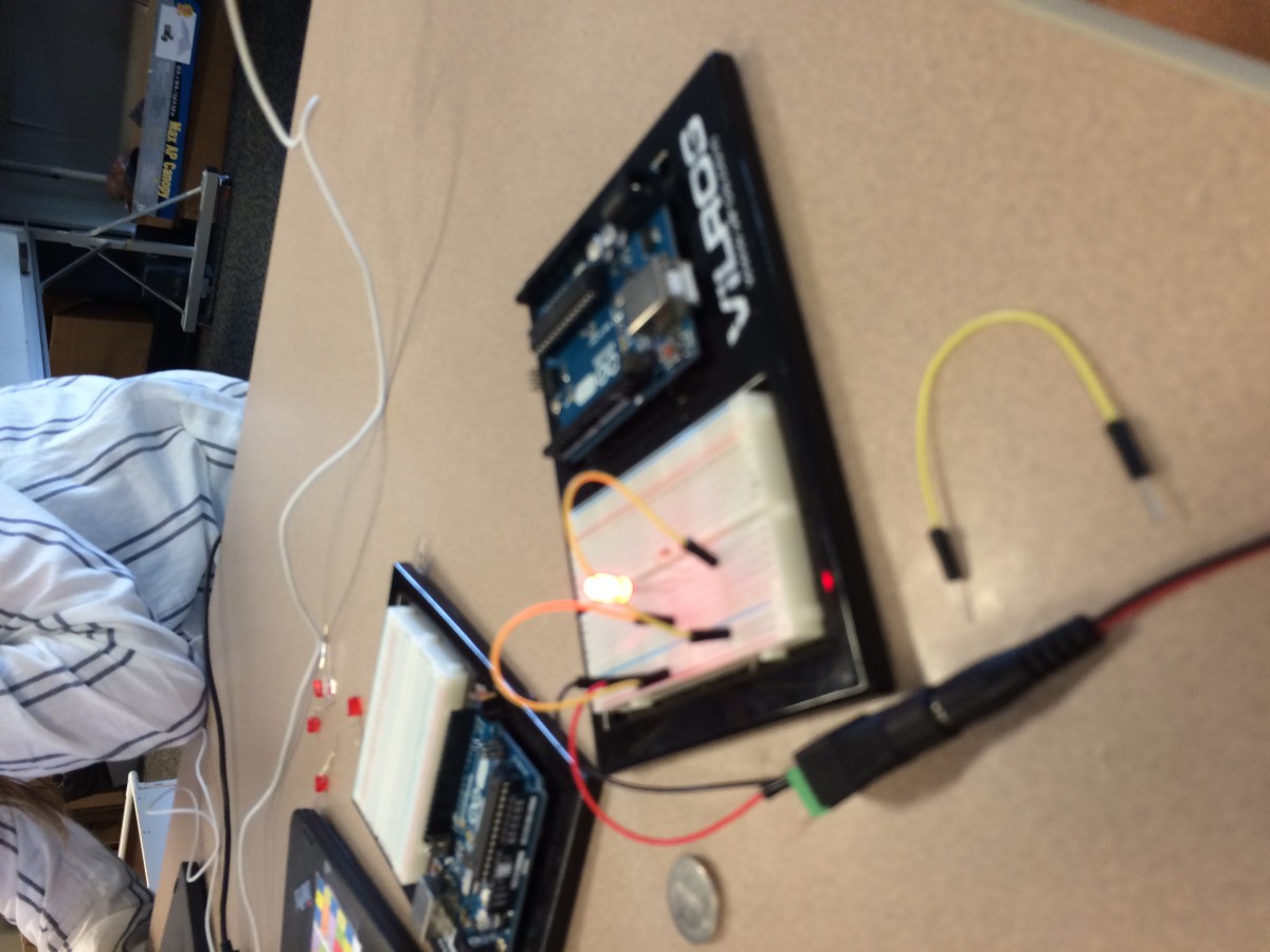


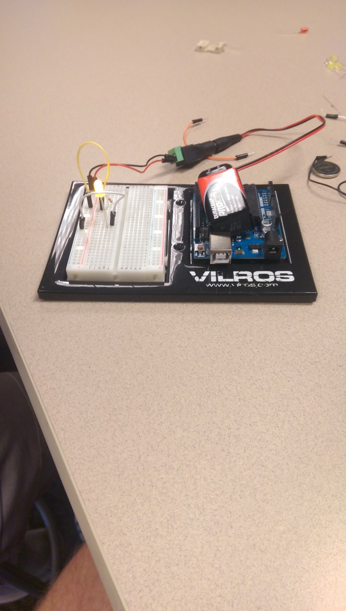


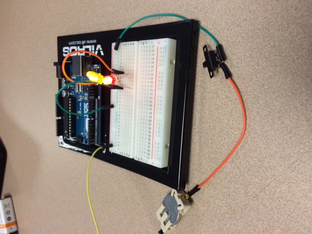

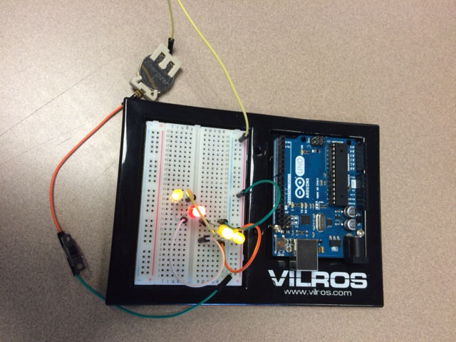

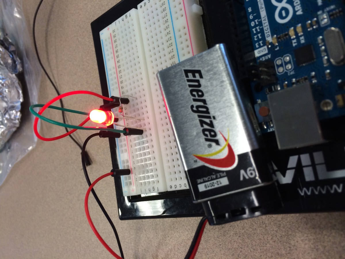
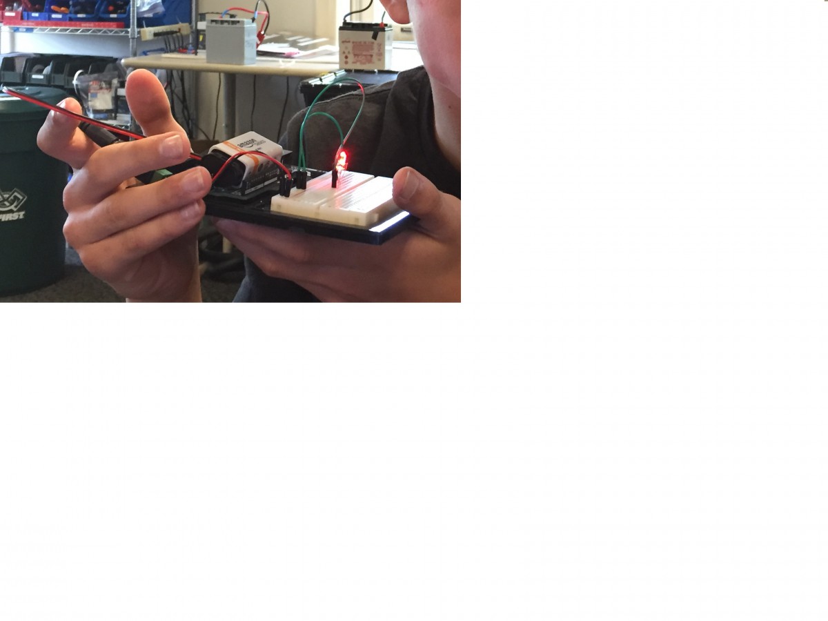
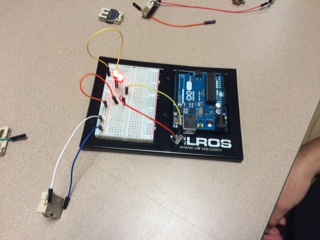
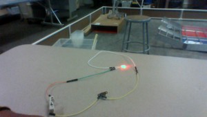
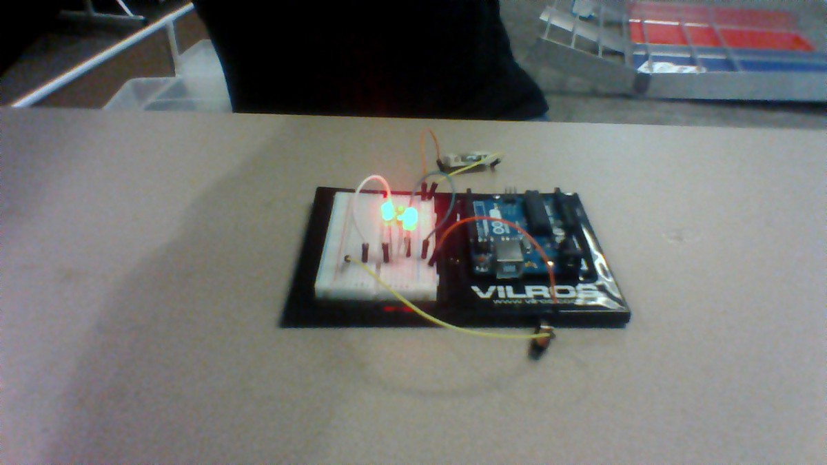
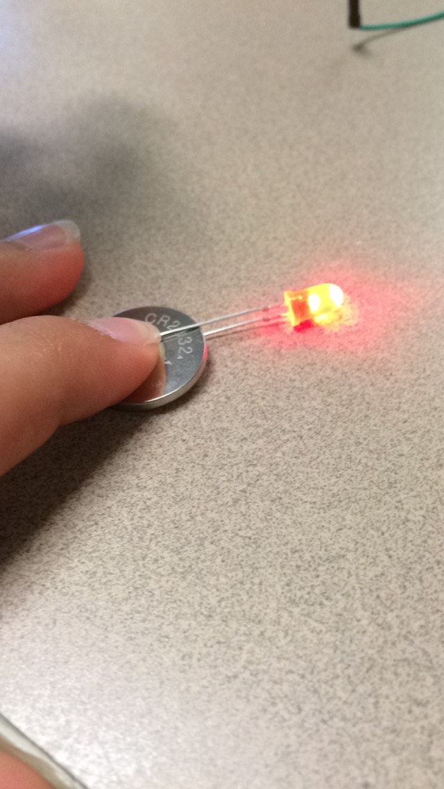
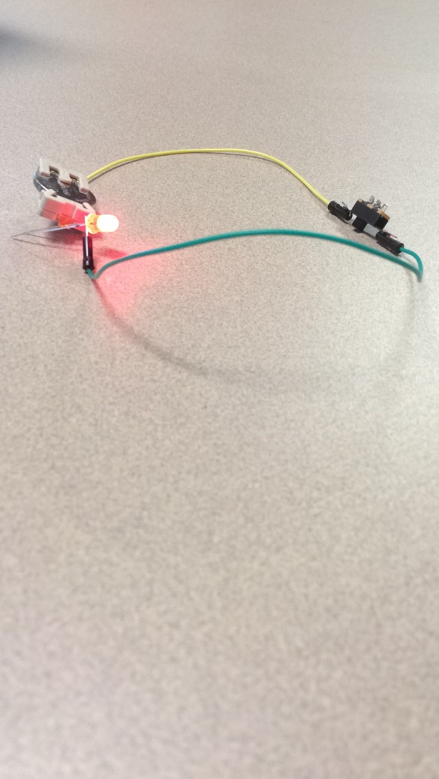
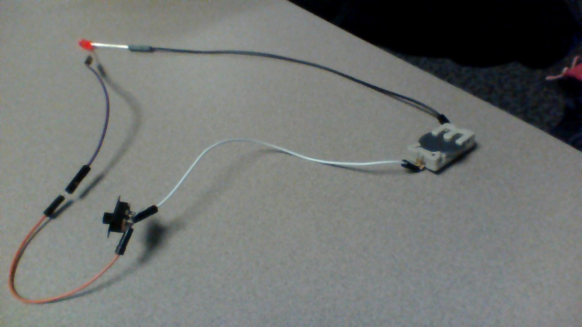
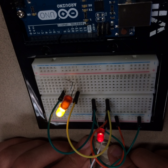
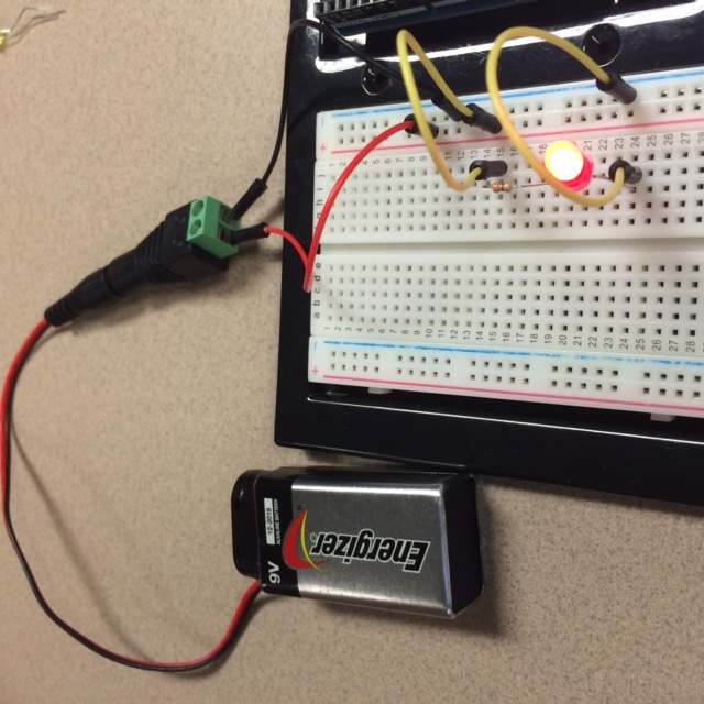
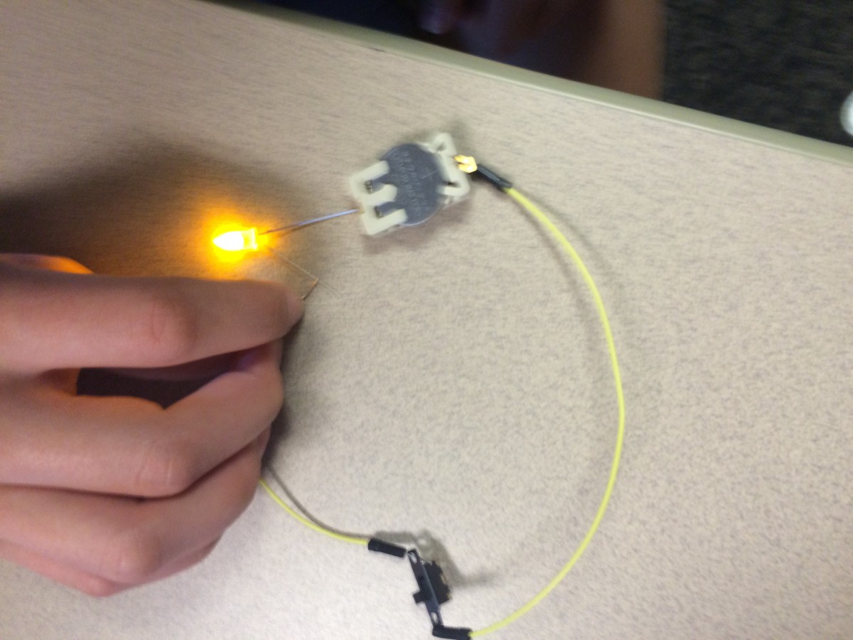
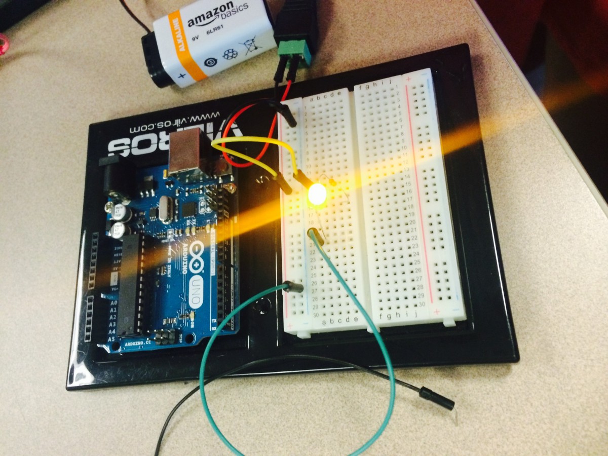
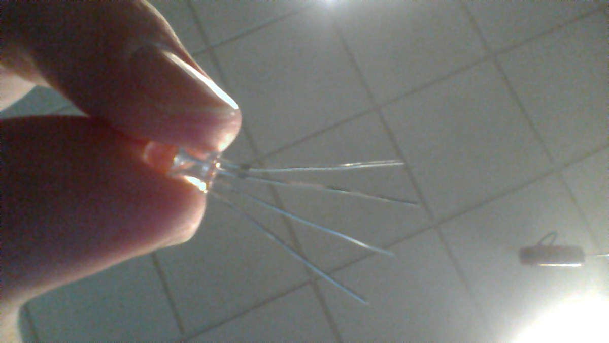
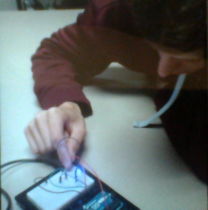
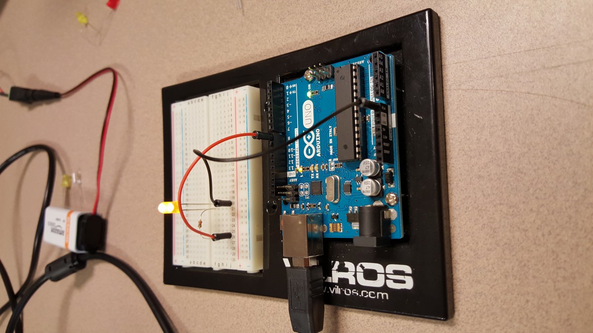
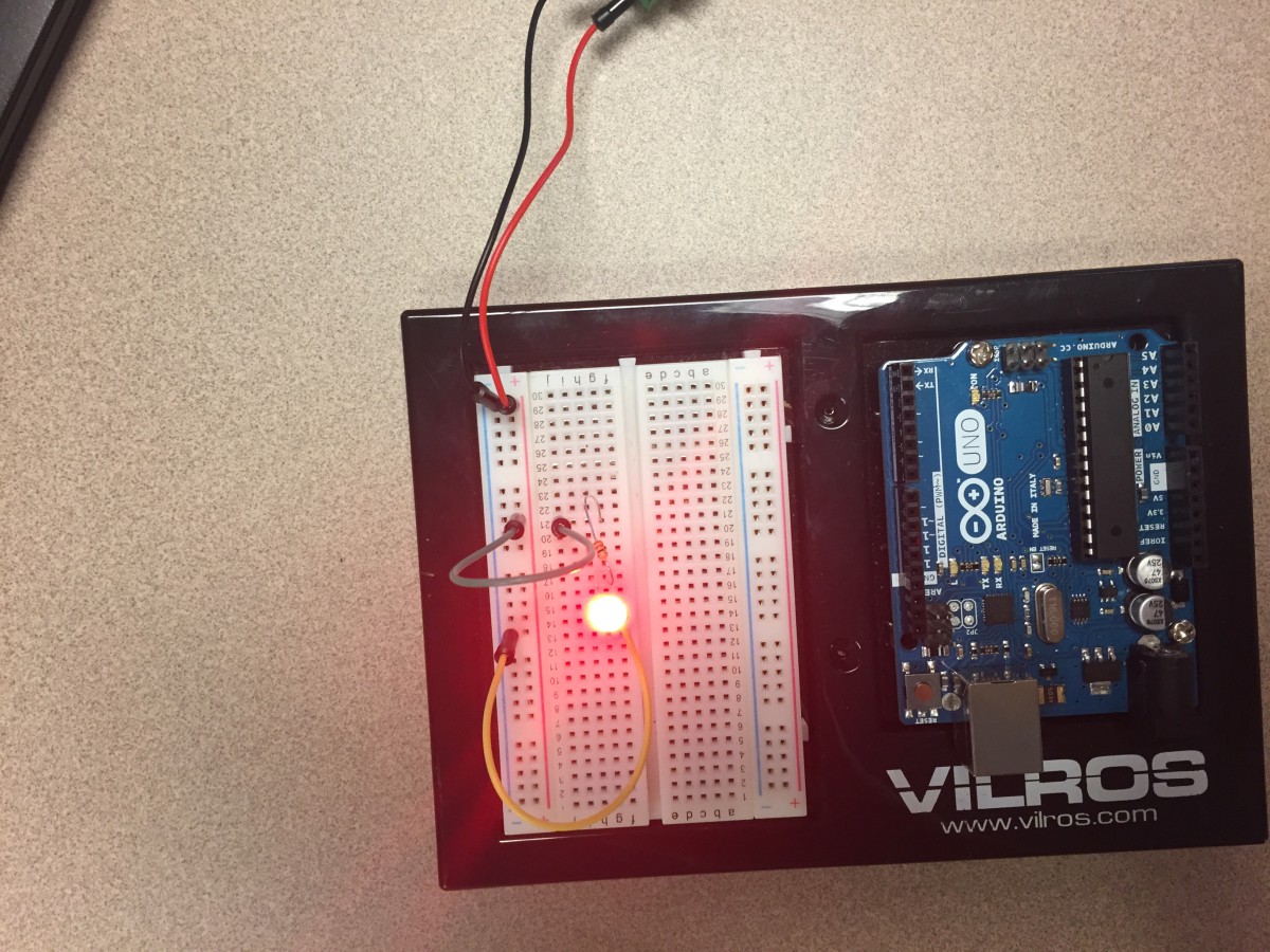
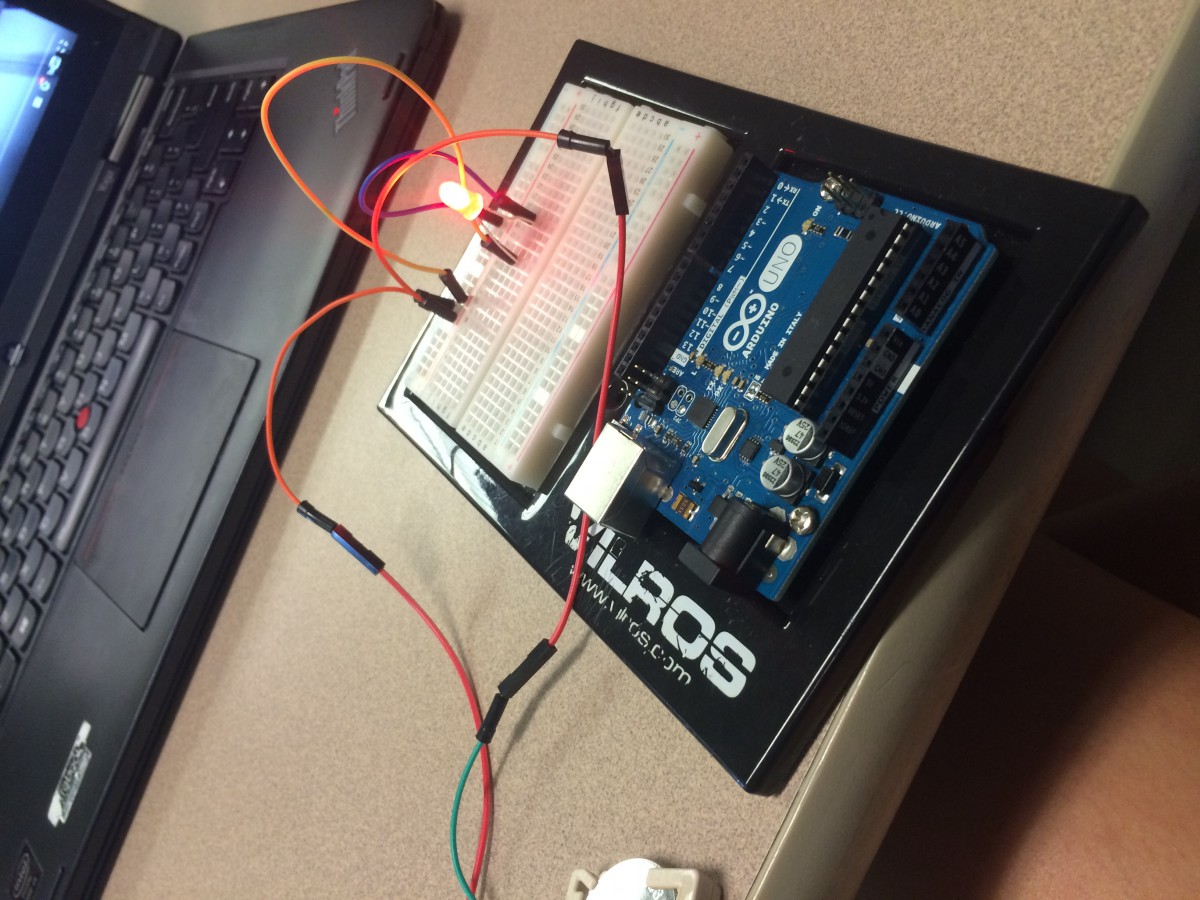
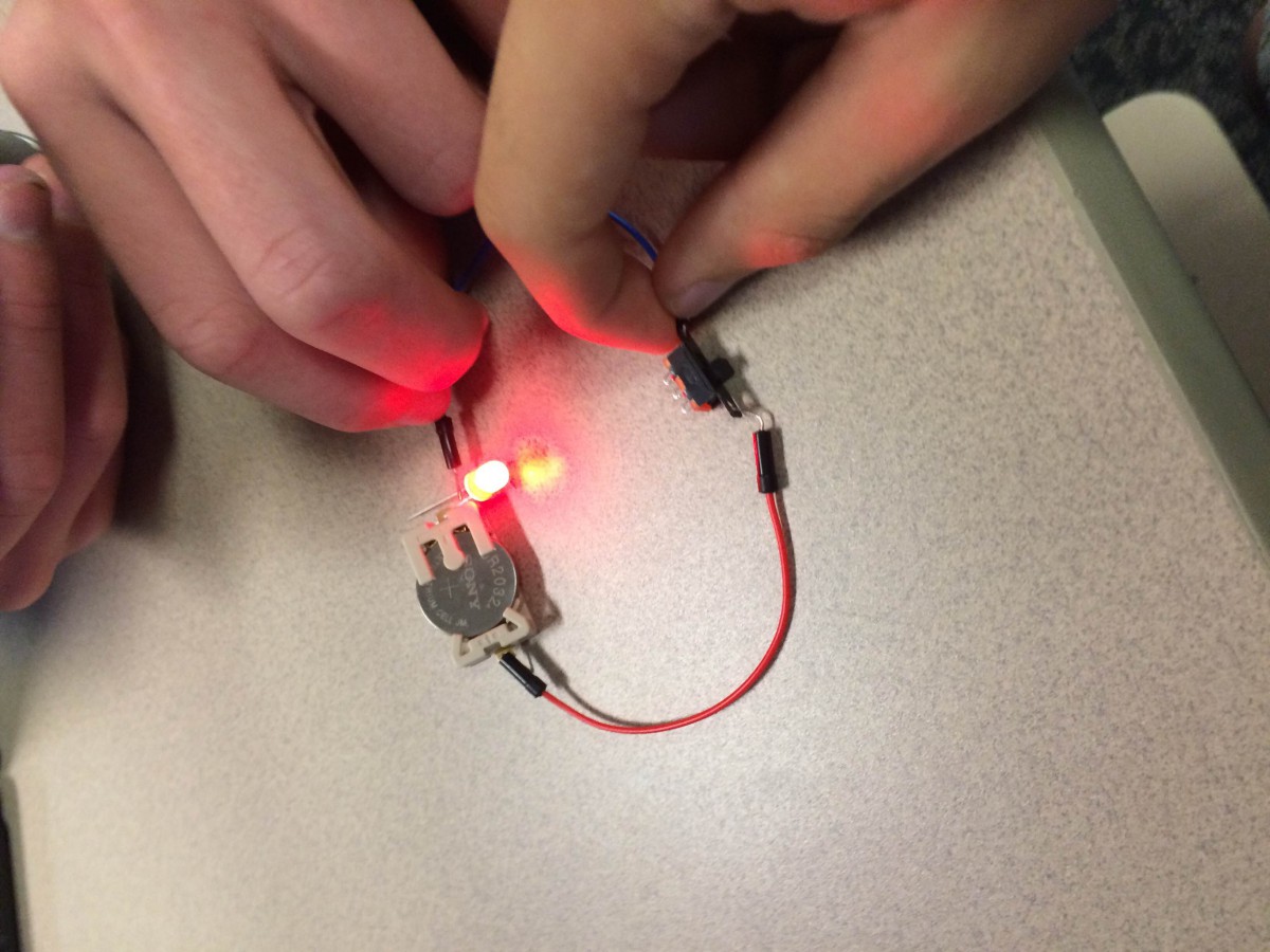
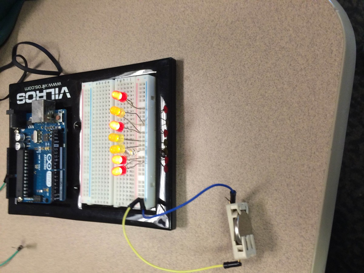
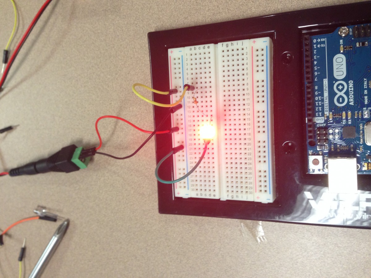
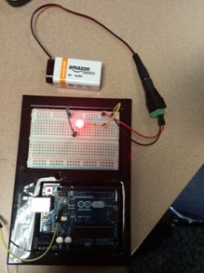
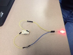
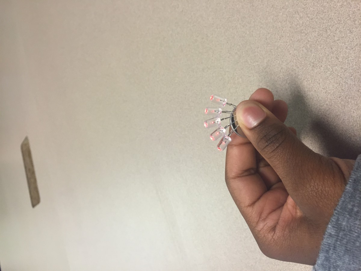
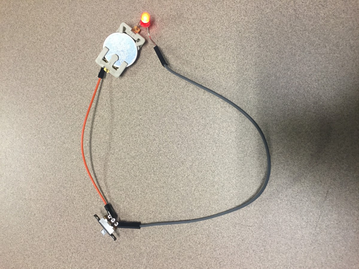
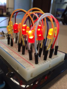 ow many LED’s can one 3V battery power?! Apparently, at least 15! (3rd image). Lastly, I learned how to use a resistor. A resistor is needed to convert the voltage from the 9V battery to a lower voltage so it won’t overpower the LED bulb, which only needs about 2-3V of power (4th image). Overall, I learned a lot about LED lights throughout this unit, and I can’t wait to do more with them!