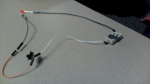
The first thing I learned was how to connect a circuit with a switch to have control over if the LED light would turn on or off by just using the switch. I used two male cords, one on the negative side and another (male and female chord) on the positive side. The positive side where the male and female side was , I connected it to the longer side of the LED light which is the longest leg. For the negative male chord I connected it to a female chord, and finally after attaching the two male chords to the switch I turned the switch on and the LED light turned on.
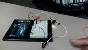
The second thing I learned was how to use a bread board. Using four male chords on the one metal bar side I connected one of them to the other side (it was a negative) and the other chord I did same, only difference is that chord was connected to the positive side. The third male chord which is on the same metal bar as the others is connected to the positive hole and also connected to the switch which powers the circuit. The fourth male chord is on the same metal bard as the others and connects to the negative side of the coin holder. The positive side of the coin holder has another chord which connects the negative side to the switch. When you add an LED light you add it next to the two first chords which crossed the boarder of the bread board, turn on the switch and the light turned on.
To use a 9v battery you need a resister. Stick the positive end of the battery to the positive channel and the negative to the negative channel. When you take a wire, put it into the positive channel and then anywhere else on the breadboard. With the resister they don’t have positive or negative ends. Pug the resister in the same column as the battery then any other colum. With the LED put it in the same row to the resister then anywhere else on the breadboard. Taking the short leg of the LED completes the circuit and turns it on.


