Tag Archives: arduino

Robotics Progress

IMG_2294IMG_2302IMG_2300

So far during our group project in robotics, we have successfully made two motors spin while connected to an arduino and one arduino connect to our computers via blue tooth. We have done this by hooking up batteries to the bread boards, connecting the motor controls to the arduino and the motors to the bread board. On the blue tooth module, we have connected it to the arduino and the bread board. We have connected all the motors to the computers through cables. Our next step is to create a chassis and be able to control the motors with wheel through a device.


Robotics blog

AS a team we have completed two motors connected to bread boards and arduinos we can control the motors and change their speed. Also we are building a bluetooth system. We now need to connect the motor to the bluetooth and put it all on a chassis. We have done this by hooking up a motor to a bread board and arduino and connecting it to a computer that we coded on.

bluetoothbig battery

LED Life

LED it up 1LED it upI learned several things from watching the LED it Up videos. First of all I learned how to make LEDs light up in general with simple batteries, and then I learned how to create circuits and how they work. LED lights have one longer side and one shorter, which are negative and positive which relates to the sides of the battery that they need to be on. Circuits use female female, male male, and female male wires in order to create a loop of energy. You need a battery and the light in general, but you need a resistor if the battery has too much energy

LED it Up!

When we did this project, I was sick therefore absent. However at home I did watch the videos. I thought the videos were cool and I wish I had the opportunity to go through these different lighting and conductor techniques. It seemed like you needed to have nimble fingers and lots of patience to try to get it to work. I know that we need to attach the connectors to positive and negative to keep the energy traveling, but will continue to ask questions if I do not understand.

LED blog

three things that i learned is that i learned that you have to place the LED light with the south on the north and the north on the south in order for it to work correctly. i also learned that jumper wires are very helpful when trying to create a full circuit. the last thing that i learned is that you need a resistor to make sure that you do not blow the LED light. In this class i made a series  of circuits that was able to turn on an LED light. i used jumper wires, “dimes” female and male wires, a resister, a battery, and an LED light. WIN_20150916_143320WIN_20150916_143259

LED it Up

When doing the Arduinos today I learned a few things. First, I learned how negative and positive charges and connections work, and how to get power to the light. I also learned what a resistor does, and why we need to use them. I also learned how to write a code in the Arduino program and upload it to the Arduino. We made 2 boards, here are the pictures.

IMAG0322 IMAG0326

LED Light It Up

Today in class I worked with Chase on getting LED lights to light up on a bread board. We started out by watching the videos, and got a light up by following the directions. We kept going along the path of the videos, and accomplishing each step. By inspecting how the first light worked, as you can see in the photos we quickly went from 1 light, to 2 lights, to 5 and 7 lights in no time. We learned a lot about cables, female and male connectors, resistors, and how not to burn your light out.

WIN_20150916_090514

WIN_20150916_085328

WIN_20150916_090246

led lights post

I learned about male and female wires. This is important because you need to have the correct wires in order to correctly wire your motor or in this case led.

using bread boards. Bread board are ways to make numerous connections. We can put wires into inputs instead of just pressing the metal parts of the wires directly to power sources. The bread board have metal strips in them that way we can direct positive and negative charges to rows of the bread board using wires. If to much power is head toward an led you will burn it out. This is why we use resistors to slow down the amount of power going to the led.

Making circuit diagrams- I learned how to make circuit diagrams, which show the flow of energy that start from the positive of the power source (Battery) to the returning to the negative of the positive source. This completes the circuit. If you place or light in the between the circuit it shows that the battery is powering the light. you can put a switch in the circuit before the light, it represents a light switch. a switch is represented by and opening or close section in the circuit.

IMG_0593


IMG_0592


LED It Up

Today, I learned about basic circuits, some Arduino programming, and did a little experimenting with LEDs. The most basic circuit I made was taking an LED, and holding it to a watch battery. Positive charge flows in one end, negative charge in another, and the circuit is completed, the LED lights up. We did some more complicated LED lighting with an Arduino and a breadboard. By attaching the LED to a circuit capable of creating new circuits within itself, we got a multi-colored LED to light up different colors in succession.

LED It Up!

This week in Art & Design we worked on various ways to power LED lights. We used switches, 3V batteries, bread boards, 9V batteries, many wires, and LED bulbs.

The first thing I learned was what was what.  I now know which wires to use where when creating a circuit. I also learned how to connect various pieces, such as a battery or LED light, to the wires. For my first project, I used a switch to turn on and off a circuit. I learned where to put the specific positive and negative inputs and outputs and how to connect the wiring. Here is what this circuit looked like (1st switch off 2nd image switch on).

photo 1

photo 2

I also learned how to use a bread board, which is a piece of equipment where you can connect multiple things with each other. I connected as many LED’s as I could fit, and this was also connected to a switch. Hphotoow many LED’s can one 3V battery power?! Apparently, at least 15! (3rd image).  Lastly, I learned how to use a resistor. A resistor is needed to convert the voltage from the 9V battery to a lower voltage so it won’t overpower the LED bulb, which only needs about 2-3V of power (4th image). Overall, I learned a lot about LED lights throughout this unit, and I can’t wait to do more with them!

photo 4

LED it Up!

After exploring and experimenting with LED lights, cables, and bread boards, much concerning the topic was learned. First, we experimented with just wires and a coin battery. I learned the differences between positive and negative sides of the battery, and how to connect the wires. I also learned through this experimentation that there are three different basic types of wires: female-female, male-male, and male-female. The female-female wires had two openings on either side, the male-male wires had two small metal pieces on either side which fit into the female-female openings, and female-male which had an opening on one side and a wire on the other side. In addition, I learned about what a bread board was and how it functions. A bread board is a small plastic board which has many small holes on the exterior. However, below the outer layer which is plastic, there are strips of metal. Each row of small holes are all connected by one strip of metal. Therefore, when you plug in the wire into two different holes on the same line of small holes, it will create a closed circuit.

Below are pictures from some of the experiments that were performed with the LED lights:

LED Lights 1 LED lights


Investigating Arduino

Today in class, we learned the basics about circuits and Arduino.  I made 4 circuits: one with just a battery and a bulb, one with a battery, bulb, and switch, and then the aforementioned circuits with an Arduino.  We had some difficulties figuring out why the light bulb was not working at first.  we soon discovered that it was not an error on my part, but a burnt out bulb.  After that, Ms. McDonald explained how the breadboards worked.  I then had a better grasp on how and why the circuits worked to transfer energy from the battery to the light. arduino  oo arduono

LED it up!

In class, we were taught (by watching videos) how to make a circuit. We were introduced to the breadboard as well as basic wire connection. I was able to successfully complete a wire circuit and a circuit on the breadboard. My most occurring problem was mixing up positive and negative on the breadboard. When the LED was in the breadboard but not lighting up it was because not correct when it came to positive and negative.


The first picture is of the wire circuit and this one was the easiest of the two but if it was moved the wrong way the circuit would break.

The second picture is of the breadboard and this (as mentioned before) was not as easy and it is allot harder than it looks.

IMG_4866 IMG_4873

LED it up!


This week we started our adventure in the world of hobby electronics by learning the basics of circuitry. We experimented with LED’s, cables, and batteries to try to familiarize ourselves with how electrical current can be manipulated to create a circuit. I learned about how one distinguishes between and coordinates certain elements by doing things such as having one leg of the LED longer to represent the positive end. When experimenting with the bread board I learned two more specific details, that utilizing metal strips can help a current be divided into multiple columns and that a battery with voltage higher than that of the device the current is being put into will blow out the device.

IMG_8508IMG_850

Let’s LED it up

I learned many things from watching the LED it up video’s. The things I learned go from simple to more complicated. Before today I didn’t even know what a bread board is! Now I know that they are little pieces of medal underneath certain parts of the bread board that I boards made of plastic with holes in them. There are also little pieces of medal underneath this holes. You can put cables inside these holes, and the medal from underneath will complete the circuit! This circuit can them light up an LED. This is a very useful things to know. I also learned that while creating circuits it is important you know which side of is it positive and which is negative. This seems like common knowledge,  most people know that negative goes to positive and the same vice versa. But now I know when it is important and when it doesn’t matter. Last but not least, I learned that their are female and male cables that can be used to create a circuit. Male cables have wires that go out, and female cables have wires that go in. Thus, you can connect them by sticking one inside the other.  This makes life a lot easier because without them things would need to be held together with our own hands. Yet, these are only the things that I have learned from the first 5 video’s. I’ll continue watching and learn even more about circuits.

Here are 2 images of what we created:


art and design 1


art and design 2

LED it Up!

Light Switch BreadBoard

This week, in class,  we worked with Led’s, Batteries, Breadboards, switches, and wires.  We also worked with Arduino and 9 volt batteries. I learned what a bread board was and it what you can use it for. It can be used for prototyping and makes connections for you.  I also learned how to connect a battery to a LED. It was a lot simpler than I thought. The longer leg was placed on the positive side and the shorter leg on the negative side of the battery. Another thing I learned about was Arduino.  Arduino is a code writing software.  I used when I was trying to make the light blink.

LED Switch Circuit

Today we learned about how to set up a switch circuit and get an LED light to light up.  I learned the difference between a negative and positive charge and that there are three types of wires ( female-female, male-male, female-male) and how to identify them based on the holes/wires.  I learned about bread-boards and how they work, and that if you plug certain wires horizontally or vertically in a line then the charge from a battery will leave those holes charged and another light can be placed in those holes.  We managed to set up a circuit system so the light would be powered by a switch. wiredesign9-17 circut19-17

Circuitastic!!!!!

This week in art & design, we worked with LEDs, batteries, breadboards, and Arduinos. Last year, we did something similar, but we just copied circuits from a book rather than understanding what the components do. This week, I learned how to make a simple circuit with a switch:

WIN_20150917_140137

I learned that the wires conencted to the switch must be right next to each other in order to fully connect the piece of metal inside so it can complete the ciruit.

I also watched another one of Ms. Macdonald’s video tutorials and made this:

WIN_20150917_140834
I ran into trouble with getting the lights to turn on. From this, I learned that the things that are supposed to be connected must be in the same row or column on the breadboard. I also learned that the longer sides of the LEDs are the ‘ground’ side, so that made it much easier to connect it to certain wires. This was an extremely fun hands-on activity for learning about circuits, and I can’t wait to tackle the RGB LED circuits next!

LED it up

Today, I worked with a bread board. It was mostly a refresher, as I already learned how to use a breadboard last year. I refreshed my memory about where to connect wires and about how important where you insert a wire is, as misplacing it could make the entire thing not work. Something new I learned was “female wires”. Last year, we only worked with “male wires” but this year, I was introduced to female wires. The female wires really extended the many things you could do with the wires. The last thing that I learned about were batteries and battery holders. Last year we did not work with them, so they were very foreign to me; however, I soon realized how important they were in providing power for the circuits.

wires2 breadboard (2)

Intro to Circuits

Over the past two classes we have learned much about electrical circuits and how they work. We began with a very basic circuit: one that had an LED light that was connected to a 3 volt battery. Then we moved onto using 9 volt batteries with resistors. We learned that by itself a 9 volt battery is too powerful to power an LED as it will burn it out, but with a resistor a 9 volt battery only provides enough to power the LED. We then learned how to use breadboards and switches and how they both worked. We learned that with a breadboard you can power multiple LED instead of just one and that a switch allows you to decide when you want to power something. At the end we put all of this knowledge together which resulted in a breadboard powering multiple LED lights that had both a switch and a resistor.

Here is us powering a breadboard with a 3v battery:

IMG_1091


Here later along is us powering the breadboard with a 9v battery using a resistor:

IMG_1092

Circuits and Switches

I am not the kind of person that has an easy time understanding circuits and how they work. By working with my partner, and watching a series of videos, I was amazed at what we learned how to do. We learned how to use a battery to make an LED light turn on. I learned that in order to turn it on you have to match up the negative side with the positive side.

Simple Battery Light Connection

The second thing that I learned is how to use the wires to make the LED light turn on. We connected one wire to the battery (in a holder), and the LED light to the other side. The wire was then connected to the switch and then to the LED light.

Basic Circuit with Switch

The third thing that we accomplished was the breadboard. We put a series of wires into certain spots on the breadboard along with an LED light(s). I learned that to put more lights in it you have to put them in the same column as the first light.

Breadboard 1

WIN_20150917_112600 WIN_20150917_114635


The first thing I learned was how to connect a circuit with a switch to have control over if the LED light would turn on or off by just using the switch. I used two male cords, one on the negative side and another (male and female chord) on the positive side. The positive side where the male and female side was , I connected it to the longer side of the LED light which is the longest leg. For the negative male chord I connected it to a female chord, and finally after attaching the two male chords to the switch I turned the switch on and the LED light turned on.

The second thing I learned was how to use a bread board. Using four male chords on the one metal bar side I connected one of them to the other side (it was a negative) and the other chord I did same, only difference is that chord was connected to the positive side. The third male chord which is on the same metal bar as the others is connected to the positive hole and also connected to the switch which powers the circuit. The fourth male chord is on the same metal bard as the others and connects to the negative side of the coin holder. The positive side of the coin holder has another chord which connects the negative side to the switch. When you add an LED light you add it next to the two first chords which crossed the boarder of the bread board, turn on the switch and the light turned on.

To use a 9v battery you need a resister. Stick the positive end of the battery to the positive channel and the negative to the negative channel. When you take a wire, put it into the positive channel and then anywhere else on the breadboard. With the resister they don’t have positive or negative ends. Pug the resister in the same column as the battery then any other colum. With the LED put it in the same row  to the resister then anywhere else on the breadboard. Taking the short leg of the LED completes the circuit and turns it on.

LED WORK WITH ABE

Today I learned about switches and how they work. We did several experiments with turning an LED off and on with the switch. I also learned about the difference between Cathodes and Anodes; cathodes are negative while Anodes are positive. I also learned about soldering irons, and how they are hot and NOT FOR TOUCHING. IMG_1097

Circuitry or Sorcery

This week in Art and Design, we learned how to set up simple circuits. First we learned the most basic principle of how electricity flows through a circuit, so that we could design closed circuits that worked. Otherwise we’d end up with circuits that didn’t have a closed path for electrons to flow through. Then we learned how to set up our circuits on a breadboard and how electricity flows on a breadboard. At first it was a little complicated, but then the pieces started to fall in place with practice. While dealing with breadboards we learned the difference between series circuits and parallel circuits, and how to incorporate resistors, and switches into our breadboards. Lastly, we also learned how to read and draw basic circuits on paper so that we could give and receive instructions, as to how to set up a circuit.

First LED Circuit            More complicated LED Circuit

Circuits and Switches

Today we worked with LED lights, circuits, breadboards, and switches.

The most basic thing that I learned was how to light up an LED with a 3V battery.  You have to match the correct side together in order to get it to light up.  The positive has to be connected to the negative and reverse for the other side.  By simply touching the prongs to the battery it immediately lights up. Without wires or switched the light bulb lit up! See picture below

Battery and light


I learned how to use a switch in a circuit.  We connected two wires on each end of the battery pack.  We then put the battery in the holder.  We connected one wire to the bottom of the switch.  Then take one of the prongs and connect it in another hole.  We then connected the other wire to the other prong of the LED.  The switch allowed us to control the flow of electricity from the battery,

basic circuit with switch


I learned how to look up multiple LED’s on to the breadboard.  I learned how to connect circuits on different parts on the breadboard.  We connected the battery to a switch that was connected to the breadboard.  We then connected the wires to another part of the breadboard.  This connect the circuit so that the lights could light up.  After doing this we could put in more lights as long as they were in the same rows.  See picture below

breadbord with light

LED it Up…

Blog about what you learned from LED it Up..

We learned how to make a circuit and connect it. I watched the videos and learned about anode and cathode and the ways that the positive and negative sides affect how you have to hook up the circuit. We also learned how to work with an LED light and make it do different things based on the program. Our groupd was also introduced to RGB LED lights, but I didn’t get to finish much besides watching the video.


IMG_1097 IMG_1098

Circuit Beginnings

This week in Art & Design, I learned a lot about how circuits work. I learned that is very easy to create a working circuit. For example, we simply put the positive side of a 3V battery on the positive wire of the LED and the negative side of the battery against the negative wire and the circuit was completed, and the LED lit up. I also learned that it is very easy to burn an LED out, especially with a 9V battery, because too much voltage enters the LED, and it overloads its relatively small electric capacity. I also learned the resistors make it possible to prevent this. Resistors take the electricity from the 9V battery, or any other battery, and reduce the charge so things that take a low amount of voltage to run, such as LEDs, will not burn out. Resistors were very helpful when  working with the breadboard.

Here are a couple of my circuits:

circuit circuit 2

LED it up!

While learning about circuits the first thing that we did was learn about how to light up LEDs using a coin battery. To light up the LED we plugged in the positive wire to the positive side, then we did the same with the negative. We connected the jumper cables to the LED and made them light up. After this, we watched a video explaining how to create a simple circuit. We used this diagram to create a simple circuit with a switch and came out successful. Next, we connected the positives and negatives on the breadboard and made the LEDs light up. We used jumper cables and male and female connectors. We learned that the two parts of the breadboard that were split up are not connected, but we can connect them by using jumper cables, in case we needed to add more lights to the breadboard. Lastly, we learned how to make a diagram for a circuit with a resistor. It is like the normal simple circuit diagram but, a little bit more complicated.

Overall, I think that we learned a lot about how to create circuits using coin batteries, jumper cables, male to female cables, a breadboard, and a switch. I think that in the future I would be able to successfully light up LED lights on my own.

circuits
Lighting LED’s with a coin battery
Circuits 2
Simple circuit on a breadboard with a switch
Circuits 3
Lighting up LED with a switch circuit
Circuits 9
Lighting up multiple LED’s on a breadboard on both parts using jumper cables

LED It Up

I learned many things during my experience learning about LED’s, breadboards, circuits, wires, etc. One specific thing that I learned is that wires can be either male, female, or male/female. Each wire has 2 ends, the end either having a piece of wire coming out or having a hole. The female wires have the wholes at the end, while the male wires have extended wire/metal at the end. In addition to learning about male and female wires I learned how to create a circuit/make an LED light up on a breadboard by creating a loop, contained of both positive and negative sides. I learned how to connect one wire to a positive row and another wire to a negative row and create a circuit by connecting the other half of the positive side and the negative side to the breadboard and creating a circuit from there. Lastly, I learned that sometimes there is too much energy going through the circuit and in order to contain the energy one must use a resistor to slow down/ limit the flow of energy.

 Circuit 1 circuit 3

LED It Up

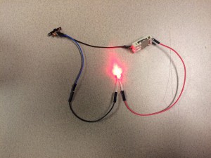
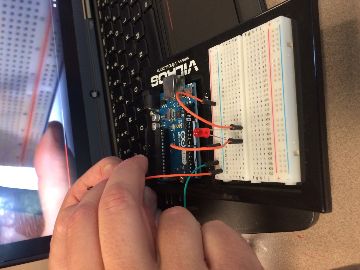
I learned many things during my experience working with breadboards, LED lights, and wires. I previously didn’t know that there were different wires- now I know there are three types- male to male, female to female, and male to female- and they all do different things. In the female to female, both sides have wires sticking out, while in the female to male only one side has a wire and the other has a connector. In the male to male, there are no wires; both sides have a connector.

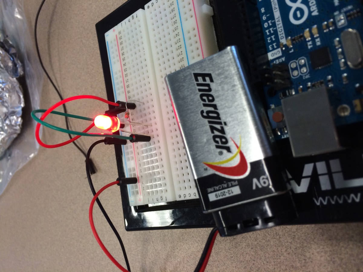
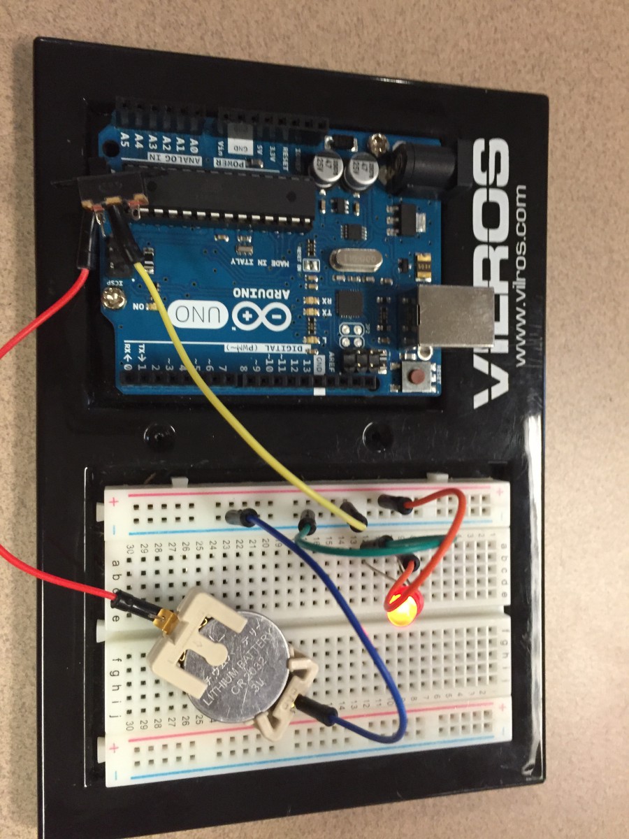
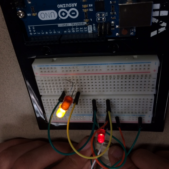
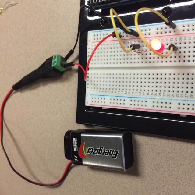
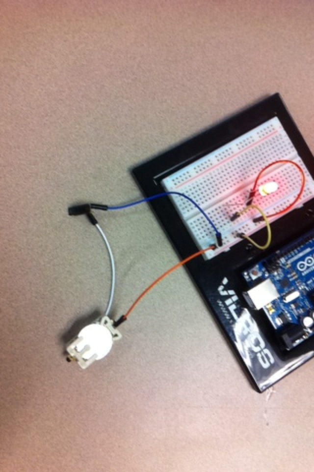
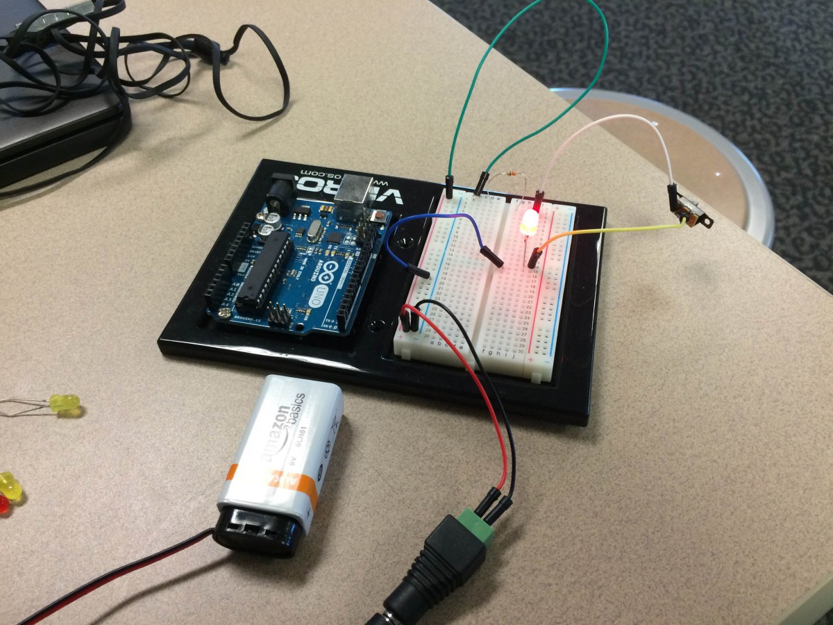
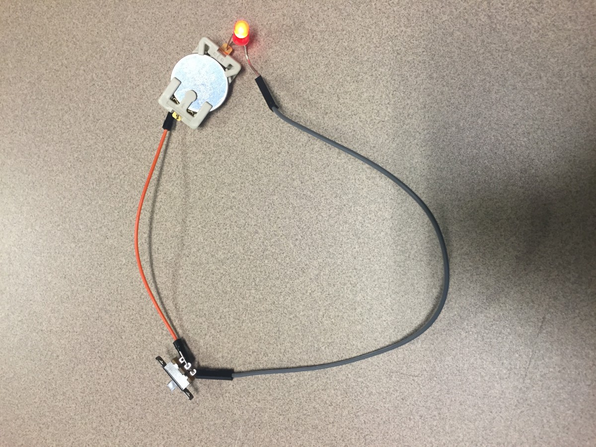
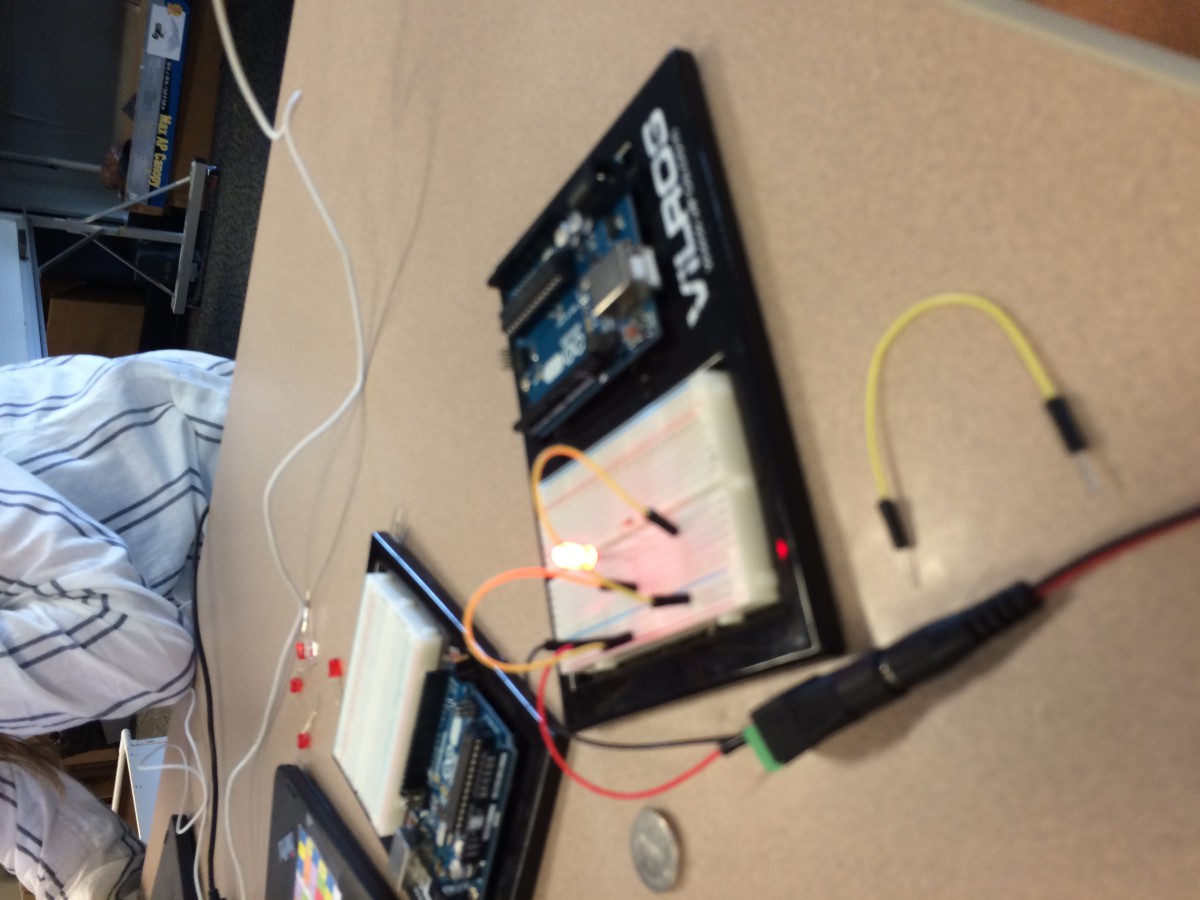
I also learned that sometimes the battery is too overpowering, so you might need a resistor to control how much energy surges through. When you put the resistor in the circuit, it slows down the flow of energy, so the LED light doesn’t get too much and blow out.

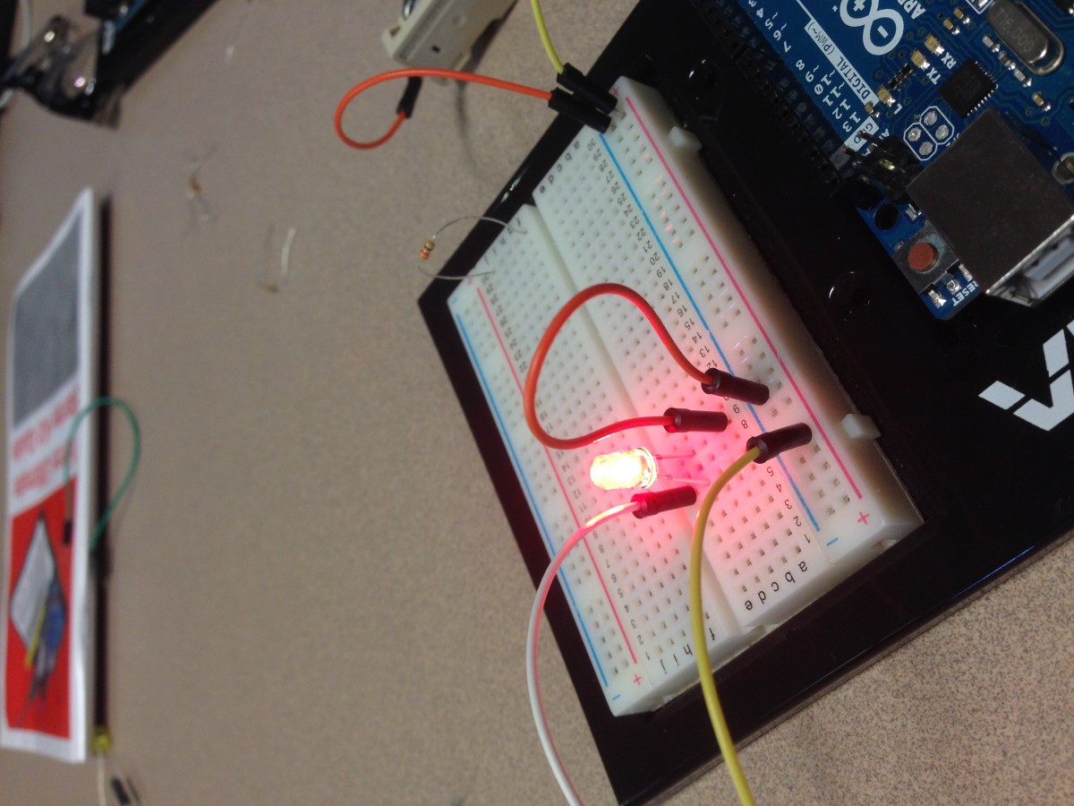
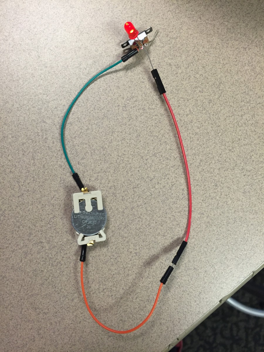
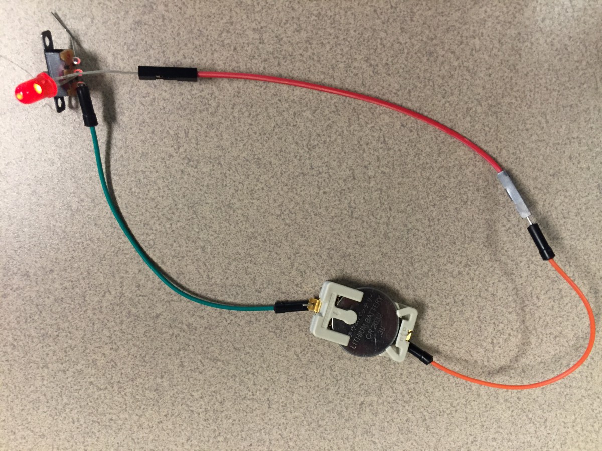
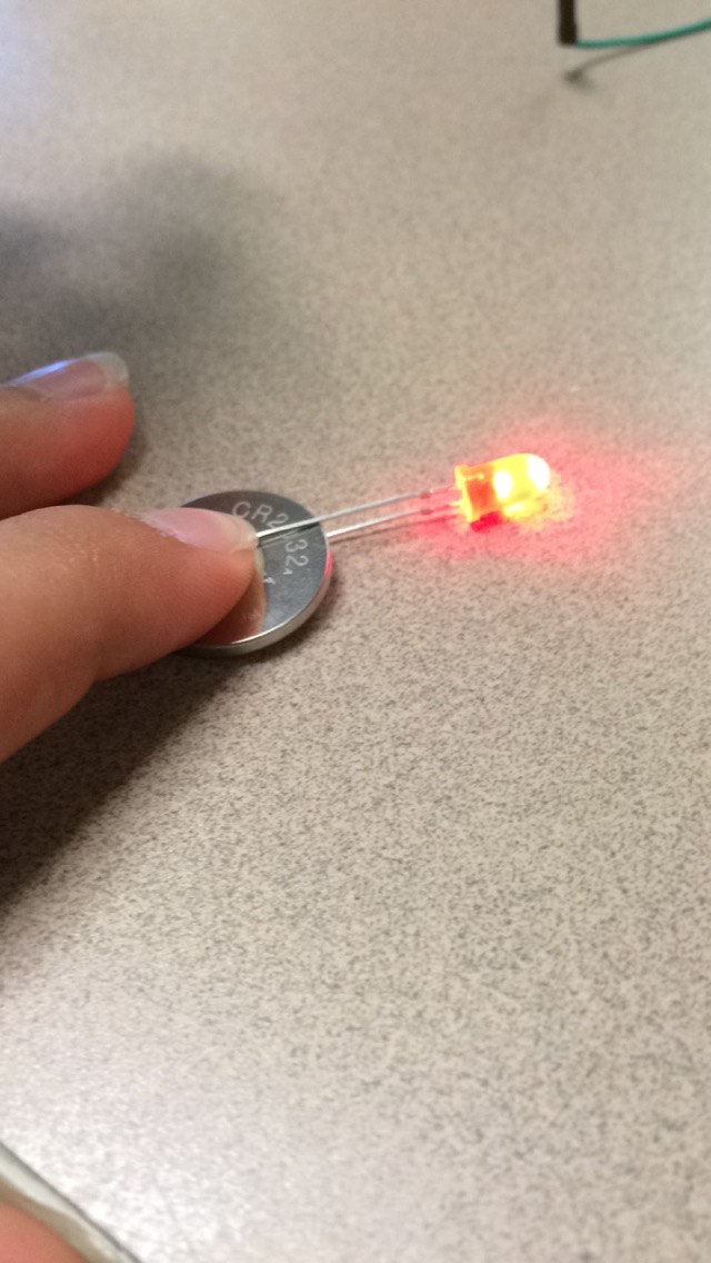
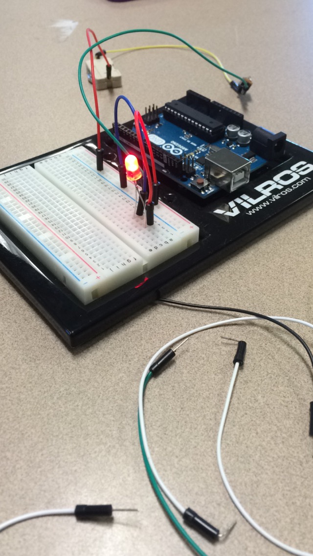
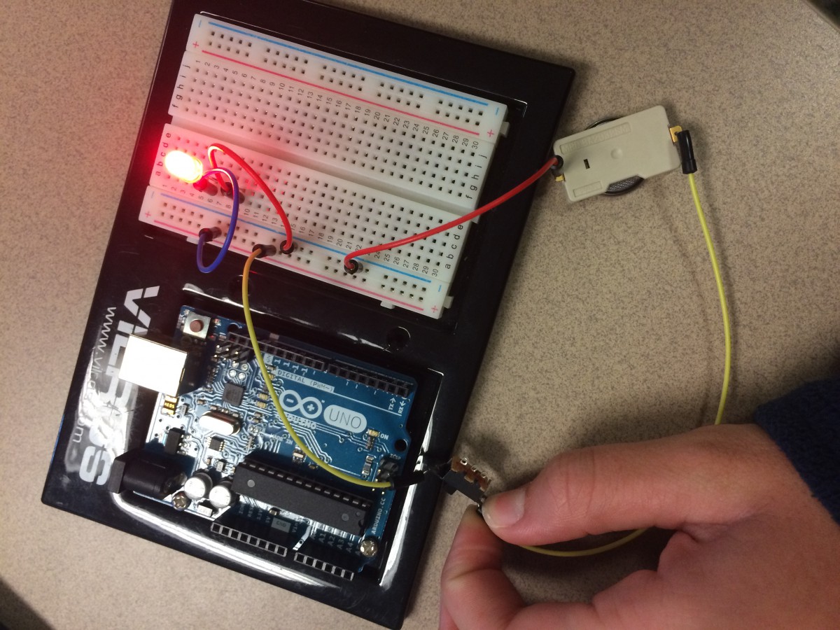
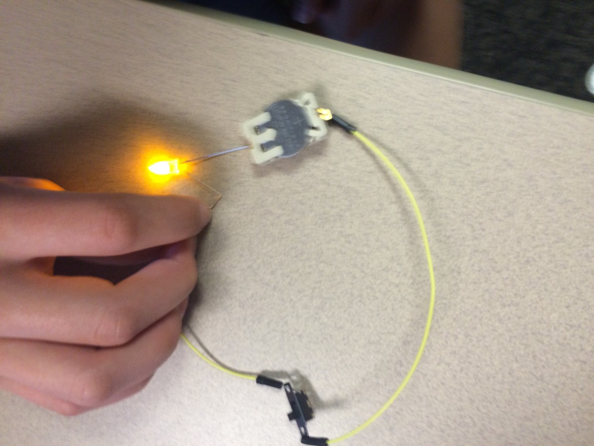
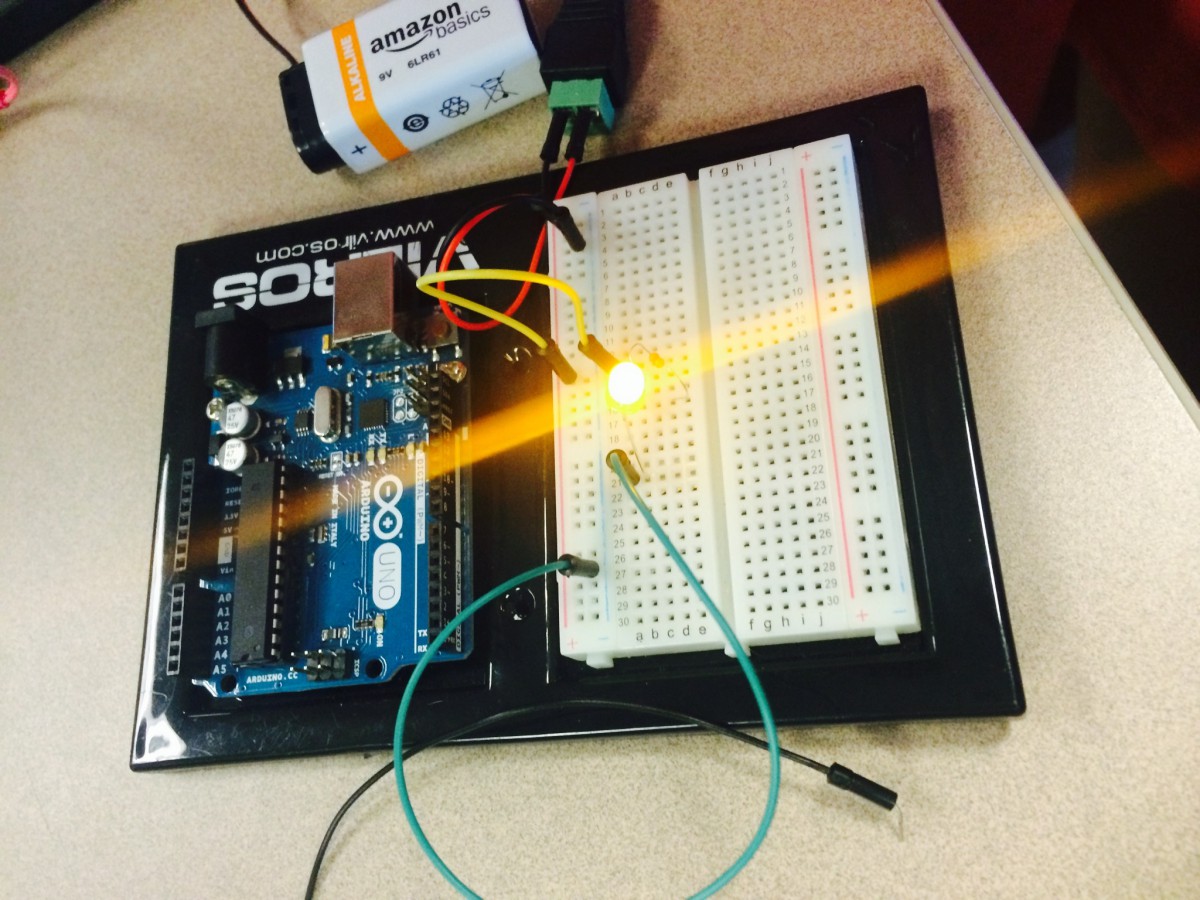
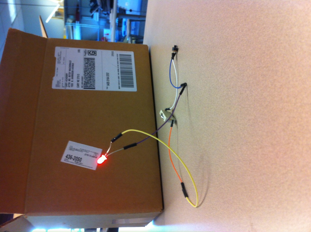
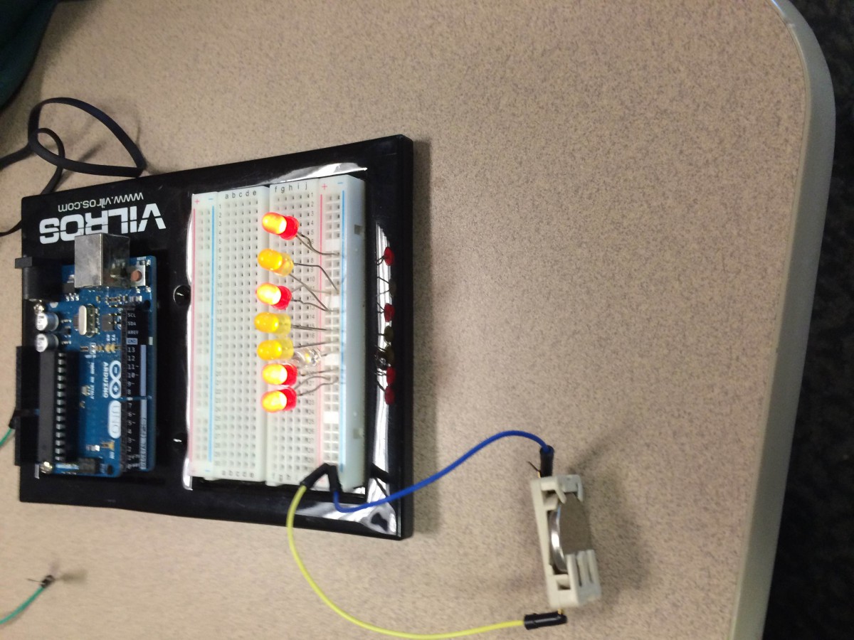
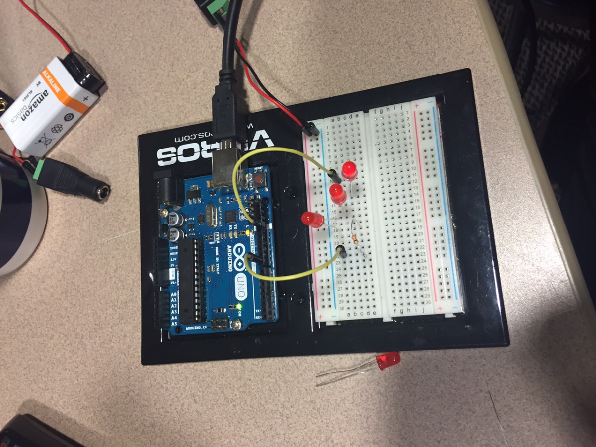
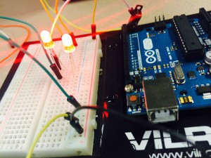
The last thing I learned was how to make a LED light up by connecting wires to the corresponding positive or negative space. I now understand how, when it’s all connected, it makes a full circuit and the energy will get to the light. If it’s not all connected, even if there’s just one space, the light will not light up. The energy cannot flow all the way through because the space that’s not connected stops it.
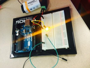
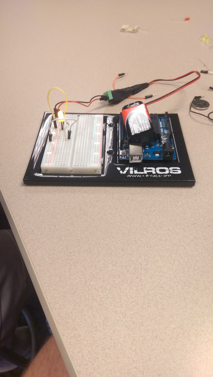
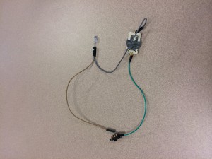
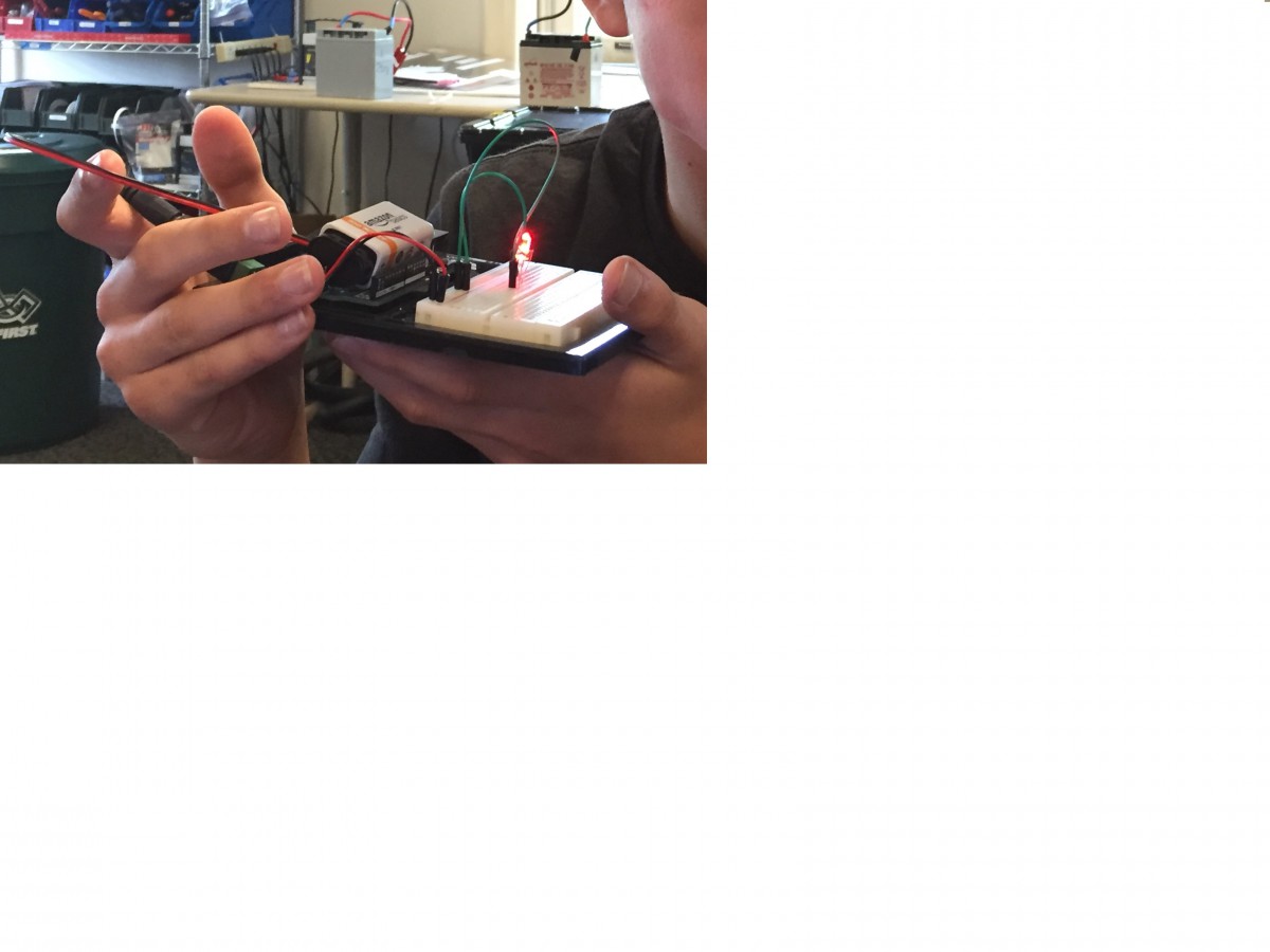
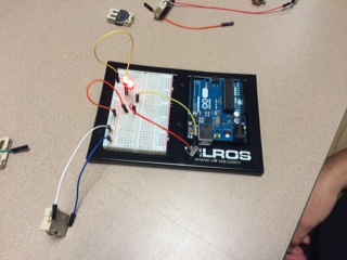
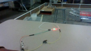
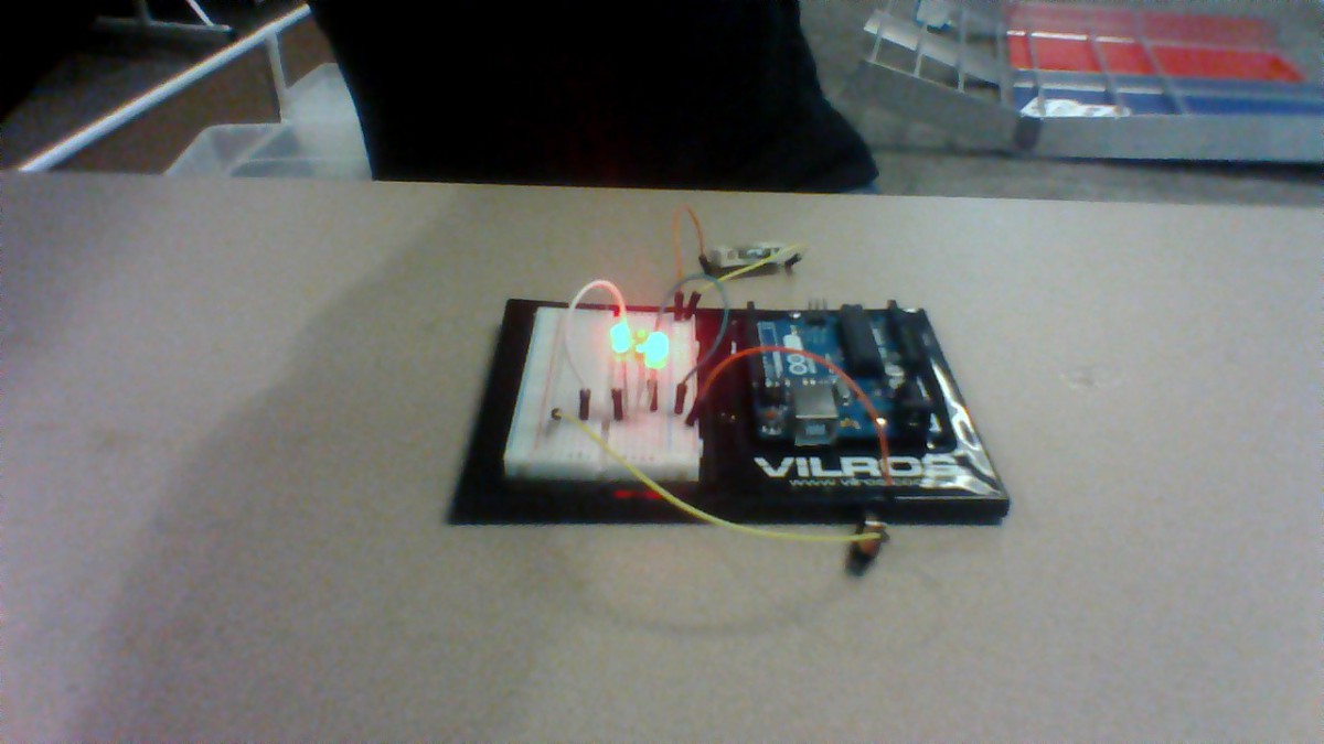
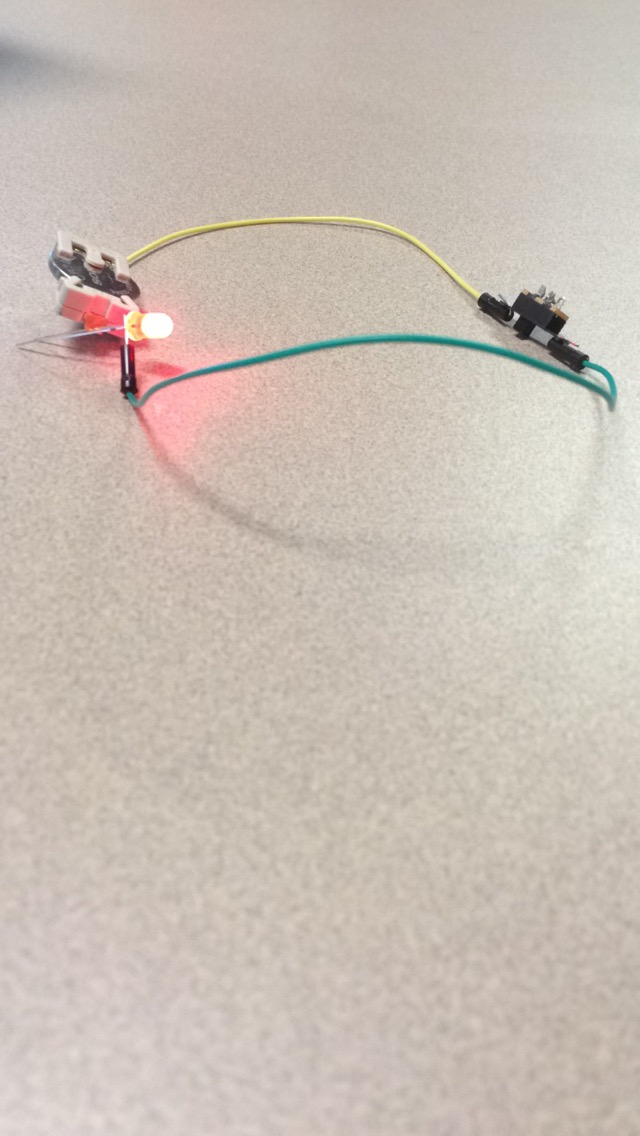
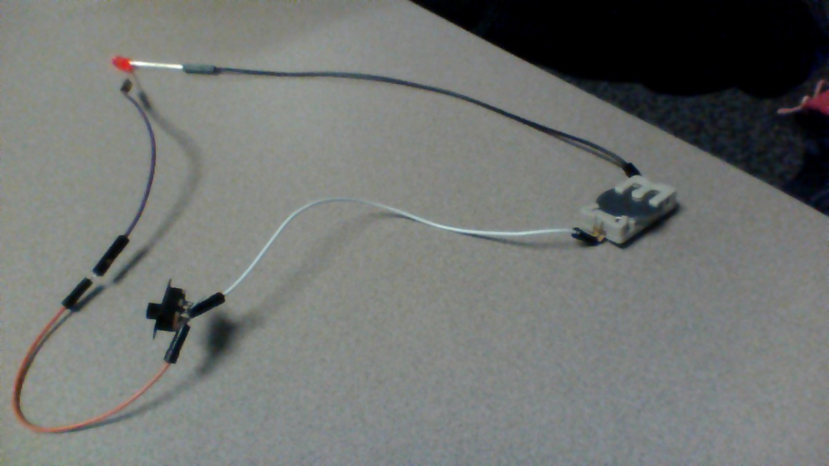
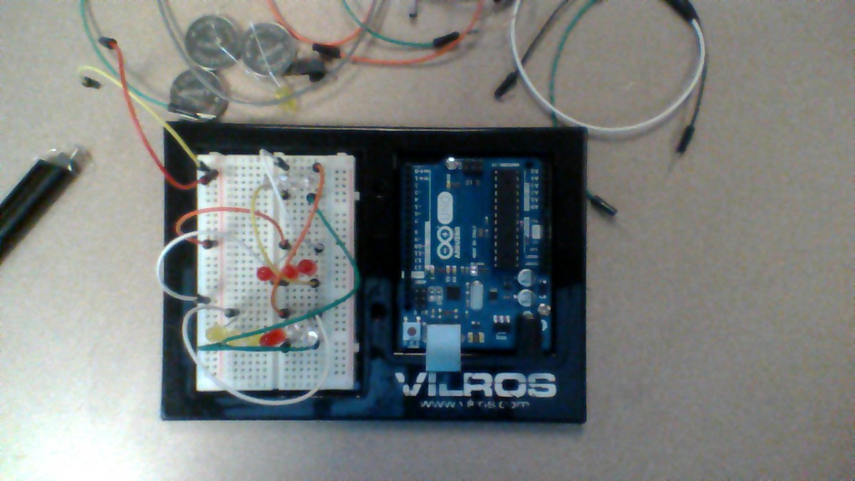
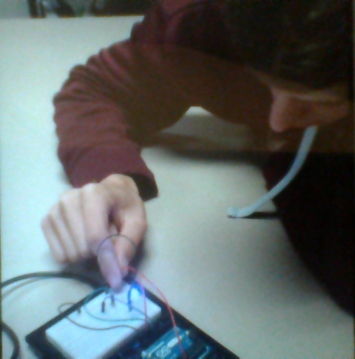
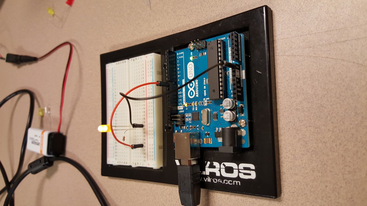
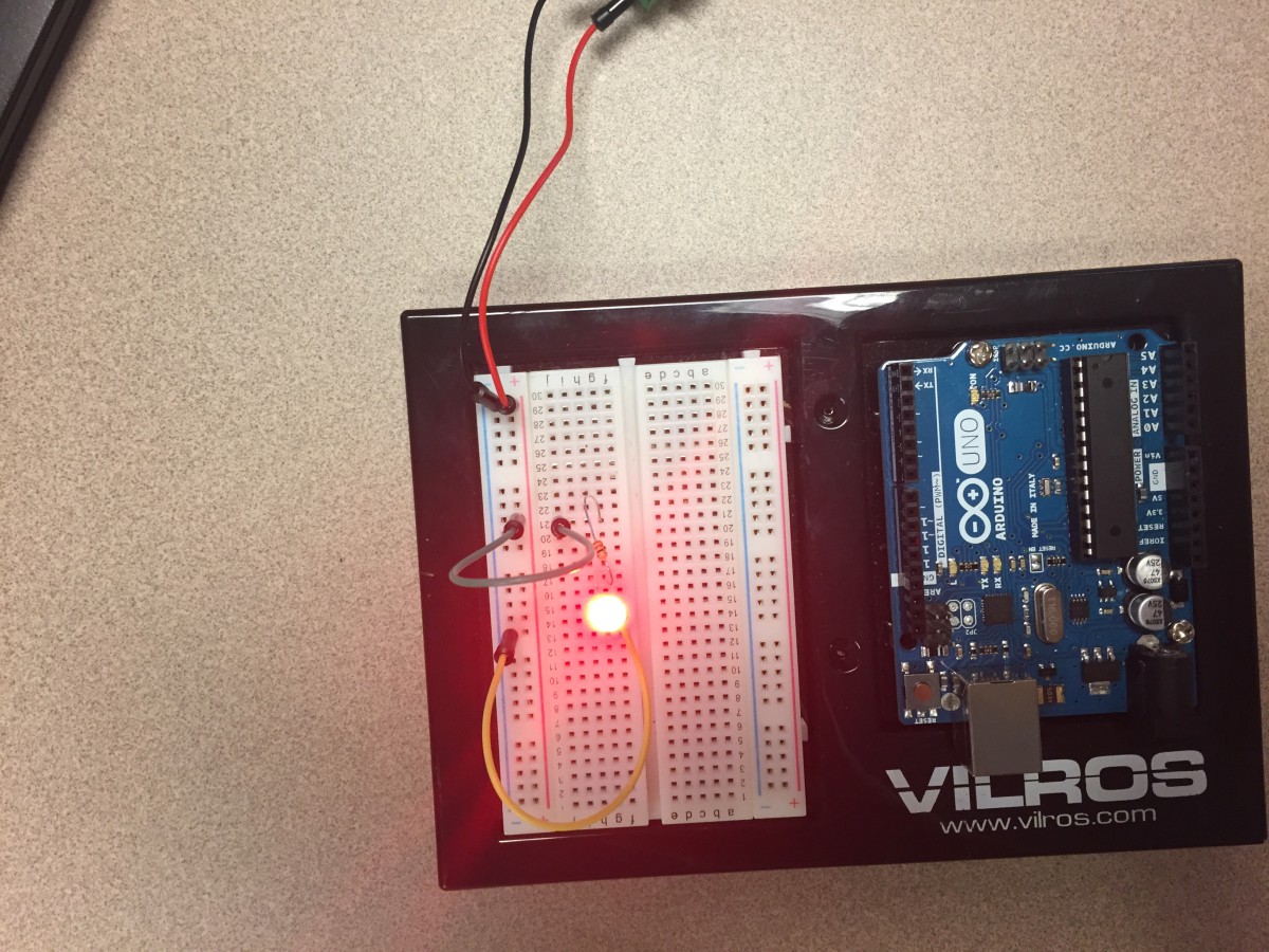
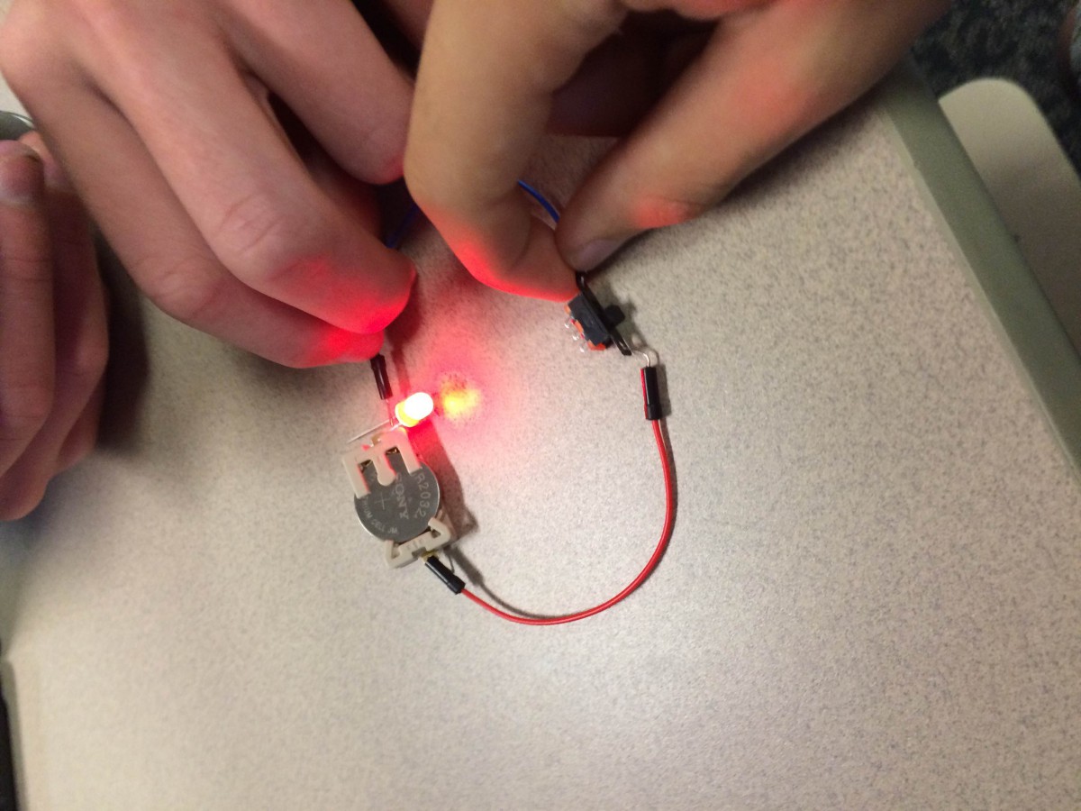
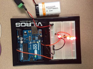
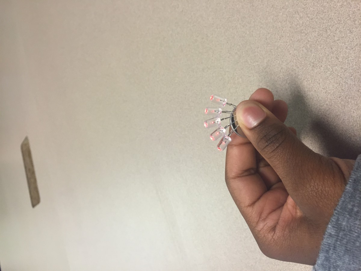
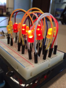
 

breadboard 1 breadboard 2


LED it up

image1 IMG_0500One thing that i learned today is that switches don’t work unless you use two ports that are right next to each other. The reason for this is because inside of the switch there is a little piece of metal that moves as you flick the switch on and off. This completes the circuit but not on the outside 2 ports. Another thing that I learned is that the color of the wire does not matter with the positive or negative sides it is just preference. Lastly I learned how a switch actually worked as I explained before.

LED It Up

During today’s work, I didn’t learn all that much.  It was a good refresher to the world of circuits and Arduino, but nothing new was really introduced except a quad-pronged RGB LED.  I also was reintroduced to switches and was corrected on my use of said switches.  We may have gone slightly overboard by adding 12 LED lights to our breadboard.

WIN_20150917_091445

WIN_20150917_091420

Arduino Expertuinos

Today we finshed up the circuit videos. We learned about how circuits work. For instance, they must be closed, or create a full, unbroken circuit. If it is not a continuous loop, it wont work. Sometimes you can use switches to control that, which have metal that slides in and out of connection. We also learned how RGB LEDs work. We had some problems making ours work, and that helped us understand it more. Lastly, we learned about resistors. I never would have thought that a simple battery could break a light, but it can. Resisters are used to basically lower the violence of the electricity so the light can handle it.

WIN_20150917_092232

WIN_20150917_092242

LED It Up

I did not know about resistors before doing this activity, I thought that any battery (one that can be bought at a regular store not some huge car one or something) could power this circuit. I did not know that if the volts were too much it could break the LED. I also learned about the breadboard, which makes it a lot easier to organize wires and make sure they go into the right place. The final thing learned was how the Arduino worked, and how I could program from my computer.

Picture 1: Lighting up the LED with a 9v battery

Pic 2

Picture 2: Making the LED blink with the Arduino

Pic 1


The two circuits above show how the breadboard, resistors, and the Arduino can be used together. The first is using resistors to allow the 9v battery to power a LED. The second one is with the Arduino and with  a computer program to make the LED blink at certain rates.

LED It Up

arduino thing 2           arduino thing 1

Today, during class, we worked with breadboards, arduinos, and LEDs. We started out by connecting batteries to a breadboard (a board of sorts that lets you connect other things to each other. We then used wires to establish connections between the battery and an LED in order to close a circuit and light the LED. We did this is various ways (as you can see above).

Three things I learned:

  • I learned how breadboards worked and how the connections worked as well.
  • I learned that LED lights are very easy to burn out
  • I learned how to connect a battery and a switch into a closed circuit.


Playing with LED’s and Circuits

What i Learned.

In class today i learned how to use a battery to light up an LED Circuit. Basically, what you do is your put this coin battery in a slot holder and attach 1 female wire to the right side of the battery and you use a female/male wire on the left side of the battery. Using the right side wire you attach it to the switch. You will need another female wire to attach to the other side of the switch.  Then, you get 1 male wire and attach it to each end of the right side female wire (attached to the switch). Lastly, you use the LED light and attach the positive side (which is the longer leg) to the male wire, and the negative leg will be attached to the female/male wire. There will be a black switch on the battery holder and you switch it on, and the LED should light up. Also using the same coin battery. Also using the coin battery, i learned how to use it in a circuit using the Arduino breadboard. First off you get two female fires and attach them to each side of the battery. On the left side of the battery you will attach a Female/Male wire to the red female wire(shown in picture below). Using the female/male wire, you put the side with the needle inside a slot on the positive side of the breadboard. Using the right side wire (which is blue in the diagram) , you plug in the other side into the negative slot on the breadboard. Then, you need another wire(white wire) and you plug in one side to the negative side of the breadboard and one into the middle space of the breadboard. Then the last wire(green wire) is plugged into the positive side of the breadboard and and then other side is plugged into the middle part of the breadboard. Lastly you need your LED. You take the LED and put it in the middle part of the Breadboard right next to the green and white wire, then your LED light should light up! Lastly, i learned how to use codes on Arduino on my computer to make my RGB light, light up. Last year i learned how to use codes, but it was never really in dept how to use them. This year i really understood how to use  them and i got my light to light up in three different flashing colors!


circuit4circuit3


SO LIT

photo 1 (00000004) photo 2 (00000002) photo 4 (00000002)I learned actually about everything that is presented here. Before this week, I came into class just knowing that electricity had to be a closed circuit to work, but now I know how to make a complicated circuit with a switch. I also learned the names of cables like female to female and male to male and female to male. I also learned how to use a resistor and how to use a switch correctly. the best part was working with the breadboard because it looked really fancy and was cool how you could power so many more things and it took a lot of fewer wires.

LED and Circuits


Today in class I learned about circuits using the bread boards and LED lights. We plugged in the wires and lights to create a full circuit. Finally we used the computers and code to cause the lights to flash. There were a lot of errors for us but switching computers helped us. We also learned how to add another flashing light but just put one into another ground and the other in the other ground slot. ledpic1ledpic2

Arduino 9/16

The first thing I learned today is the the resistor has to connect to the shorter end of the LED. Another thing I learned how to do is make a LED blink instead of it just being a stable light. I also learned how to right a code and that codes have to be exactly correct or else it will not work. We ran into a lot of troubles with our coding as well.

IMG_7159 IMG_7162

LED it Up

During “LED it up”, we learned how to create simple circuits using 3 volt and 9 volt batteries. We learned that if there is no resister on a 9 volt battery, it will almost instantly. We also used breadboards to make the circuits more easily and connected a switch to both the 9 volt and 3 volt battery. We used switches to complete and disconnect the circuits. In the end, we used an Arduino board to program a LED to blink.

IMG_0879 IMG_0881 IMG_0883

Testing out Arduino and LEDs

Today in class we learned how to use LEDs in multiple ways. While we did this we also learned what the symbols meant when drawing out a circuit and how to use the Arduino. Some of the things we did with the LEDs are a simple circuit, adding a resistor, putting a switch in the circuit, parallel wiring and RGB LEDs. You can see pictures of the simple circuit with a swtich and the parallel wiring on the breadboard. I also learned that the holes in the breadboard run parallel with each other so in order to connect the different parts of the circuit, they have to be in the same column. The resistor is used so that the 9 volt battery is not giving too much charge to the LED causing it to burn out. on top of that, the positive leg of the LED is the longer leg, and the shorter leg is the negative.  I now have a clearer understanding of how all of the components work and flow together. switch ledparallel LED

Arduino, Breadboard, and Circuiting

IMG_1565 IMG_1572 IMG_1573 IMG_1562

IMG_1564


In class we started with basics and moved into the more complicated aspects of lighting LEDs. We first determined the positive from the negative ends of lights and batteries so that we could successfully make a circuit with a 3 volt battery. Next we moved into doing that will a switch so that you can control when the light is on and off. I then proceeded to using a breadboard where you used the cables to connect to a 9 volt battery. To make it a little more complicated you added a switch to the breadboard circuit you already made. Next I made it where the light could blink using code on half a second intervals. Lastly I created it where three lights could be connected and light using programming with the Arduino.

LED lights

Today I learned how to make LED lights light up on a bread board. We got 3 lights going at the same time. It was hard at first to figure out if we had the lights in the wrong place, or if the bulb was out, but after awhile we really got the hang of it, and got 3 or 4 lights going at the same time.

We learned different ways to set up, so that with one battery we could get the lights going.

We also learned how to read the pictures and videos of them setting it up, because some of them showed a picture, that wasn’t exactly the same as we had to set it up.

WIN_20150916_084139


pic of our thing

LED Lights

Today in Art and Design Justin and I learned how to make LED Light Bulbs light up using a bread board and battery. We started with the breadboard, then with the help of the video Justin and I connected the battery into the breadboard with wires, then we connected wires from the the wires to the resistors, then the resistors to the LED lights, and then the LED lights to more wires. Also, we learned how to do multiple LED lights using minimum wires and many different arrangements of the lights using the pictures and videos provided for us. We learned the differences of the positive and negative ends of wires and bread boards, how to position the wires and resistors so that the energy from the battery would flow into the LED light, and how to create multiple lights strung together using the same links of wires.WIN_20150916_084824WIN_20150916_084139