We have successfully connected the motor to the Arduino and Breadboard. We have connected another motor to an Ardunio and Breadboard. We have also begun the first step of using Bluetooth to drive our car. Our next step in building our car would be to finish connecting Bluetooth. After that we will begin to build the frame that way we can connect all of the parts. Here are some pictures of our progress:
This is our first attempt at connecting Bluetooth. We need to finish connecting this to our computer and phone.
This is our motor successfully connected to the Ardunio, Breadboard, and synced with the computer program. We are now able to get it running on the first time.
We will also need to make a chassis as part of our new few steps.
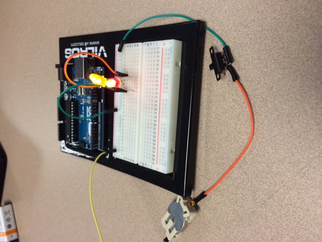
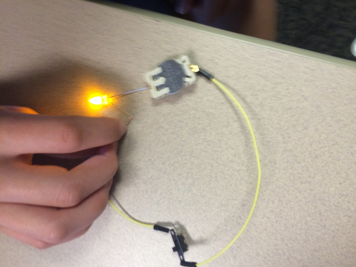
For this project, we had to watch videos in which Ms. MacDonald shows the basics of completing a circuit. In the first picture, we learned that each LED bulb has a positive and negative wire that has to correspond to the sides of the battery in order for the light to light up. In the second and third picture, we learned about breadboards and how they can complete a circuit. Both circuits contains a switch and battery along with many wires to make a complete circuit. I also learned that the breadboard has positive and negative sides that have to be used correctly for the light to work. Another thing that I learned was that the switch only works when both wires are connected to one side. There are three little holes on the switch and if the two wires that are connected to the switch are connected to the left and middle hole, then the switch has to be on the left side for the circuit to be closed. I also learned that this is true on the right side as well.
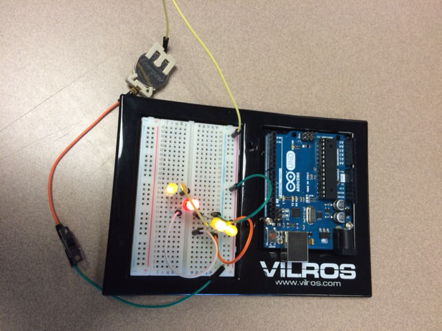
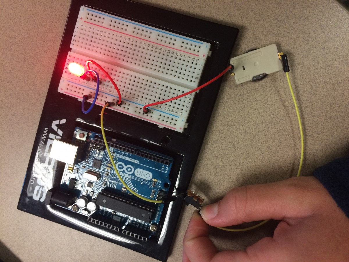
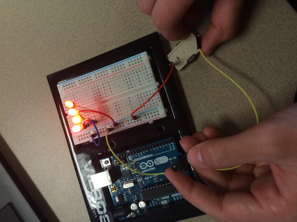
Through the videos, we learned a lot about LEDs and circuits. Some specific things that we learned was how to light up LEDs using a coin battery. To do this, you just had to connect the positive to the positive and the negative to the negative. Next, we played around with switches. We created a simple circuit using two jumper cables and connecting them to the coin battery. We then connected the two jumper cables to the ends of the switch. When we turned the switch on, the LED lit and a complete circuit was created. We then applied the same methods of making a simple/complete circuit to a breadboard. We first plugged in jumper cables to the different holes on the breadboard, making sure we connected the negatives and the positives. We then connected a switch and also a coin battery, once the switch was turned on, the LED lit up. Next, we started adding more LEDs to the breadboard and started adding them on the second part of the board. In order to create a complete circuit throughout the breadboard, you have to use jumper cables. As the picture shows, we had jumper cables that were located on both parts and therefore completed the circuit and caused the LED to light up.
These videos definitely helped me learn more about circuits and become confident in creating them. I also learned what a breadboard was and got to experiment with it!
Lighting up LEDs with a coin batteryLighting up an LED with a switch and a complete circuitSimple circuit with a breadboard and a switchLighting up LEDs on a breadboard on both parts using jumper cables