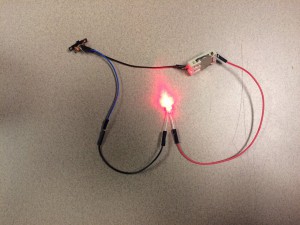
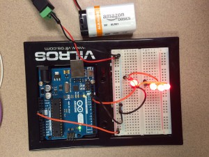
Today in class we learned how to use LEDs in multiple ways. While we did this we also learned what the symbols meant when drawing out a circuit and how to use the Arduino. Some of the things we did with the LEDs are a simple circuit, adding a resistor, putting a switch in the circuit, parallel wiring and RGB LEDs. You can see pictures of the simple circuit with a swtich and the parallel wiring on the breadboard. I also learned that the holes in the breadboard run parallel with each other so in order to connect the different parts of the circuit, they have to be in the same column. The resistor is used so that the 9 volt battery is not giving too much charge to the LED causing it to burn out. on top of that, the positive leg of the LED is the longer leg, and the shorter leg is the negative. I now have a clearer understanding of how all of the components work and flow together.